Complete solution for remote ham radio control: operate your shack from anywhere on earth. Tune frequencies, transmit (CW / RTTY / PSK31 / Olivia / APRS / voice / SSTV / WEFAX images), watch the SDR panadapter, decode twelve digital modes, and stream broadcast-quality audio to a Windows desktop, web browser, iOS / Android phone, or Home Assistant dashboard — or run the station from a rugged touchscreen tablet in the new touch mode. Single port for full remote access through Cloudflare Tunnel, Tailscale Funnel, nginx, or a port-forward, with optional HMAC-SHA-256 authentication.
From my shack to yours
I love building apps, and ShackLink is what happens when I get to blend my two favorite worlds: software and ham radio. It began as a scratch-my-own-itch project. I wanted to run my own station from anywhere, exactly the way I like it, so I built it. It grew into something I’m glad to share, so the Windows server and desktop client are completely free. When the iOS and Android apps arrive, a small charge may apply on those platforms, just enough to cover the app-store costs.
It’s still under active development and heavily in beta, so you’ll meet the odd rough edge here and there. Feedback is hugely appreciated. It genuinely steers where this goes. One friendly heads-up: there’s a lot of information on screen, so a large monitor is highly recommended. What can I say? I like my eye candy. 😄
📻 Why ShackLink?
Everything you need to control your ham radio remotely over your local network, or anywhere on the internet.
🌐 Operate From Anywhere
One unified HTTP + WebSocket port (8084) carries the entire client experience: control, audio, transmit, SDR spectrum. Wrap it in a Cloudflare Tunnel, Tailscale Funnel, or plain reverse proxy and your shack travels with you. HMAC-SHA-256 authentication (optional) gates every connection so unauthorized clients are dropped before any state is sent. Since 2026-10 the authentication settings live in %LocalAppData%\ShackLink, where an installed server can save them, and a settings file that cannot be read keeps authentication on and refuses remote clients rather than letting everyone in; the Security panel says what went wrong.
🎧 Dual Audio Streams
Two parallel audio paths: low-latency 12 kHz PCM for tuning and digital-mode work (~200 ms), and 192 kbps stereo MP3 (HiFi) for broadcast-quality listening. Clients toggle between them per-session; HiFi works in any browser / VLC / mpv just by opening the URL.
🎧 Every Client Hears Its Own Receiver
With several SDRs running, each connected client picks which one it listens to — independently of every other client, and without moving the station’s own audio. Two operators can sit on two different bands while a third keeps following the station, which is what every client does by default. The server answers each request with the effective value, so a refused or clamped selection can never leave a control disagreeing with the speakers, and a receiver that stops moves its listeners back to the station stream with an explicit notice rather than into silence. Setting the station’s audio remains a separate, labelled action, because the main decoder, the HiFi stream and the measurement instruments genuinely follow the console.
🎤 Voice Monitor — Speech to Text
Live transcription of SSB voice on the station’s own audio. Two engines behind one switch — a streaming recogniser printing word-by-word, and a chunked Whisper model that is more accurate a sentence at a time — with optional Vulkan GPU acceleration (~4× CPU, any vendor’s driver). Models download only on explicit consent and are verified against pinned checksums. It will not invent speech: a transcript must clear an independent voice-activity check, the engine’s own confidence, and a text-plausibility test before it is committed, measured at zero committed transcripts across 1000 windows of noise on both engines. The band skimmer uses the same engine to transcribe every voice signal in a segment at once. New 2026-09: transcription runs with the window closed and shows on the tab-row strip, foreign speech is transcribed in its own language, and the transcript can be translated live by a local model — no cloud service, downloads only on consent. New 2026-10: the transcript and its translation also appear on the desktop, web and mobile clients, in the decoder display they already have; the Voice Monitor keeps its transcript across a restart and can save and load it.
📊 Band Activity — And Whether You Were Looking
Which band is open, to where, how strongly, and whether it is improving or dying — assembled from eight activity sources at once. Stacked bars or a band×time heatmap over 15 min to 24 h, a “Receiving now” panel, a trend against the previous equal period, geography with distances and a bearing rose, and a station table with click-to-tune. What sets it apart is a coverage record: the server samples where its receivers actually were, so a band nobody was listening to is drawn as no claim at all rather than as a dead band. Persisted to CSV and reloaded on start.
🧱 A Workspace You Arrange
Panels dock, split, tear out into floating windows for a second monitor, and snap back. The rail carries eight rooms — Operate, Survey, Decode, Skim, Transmit, Bench, Log, Station — and clicking one restores that room’s whole arrangement rather than selecting a tab; Assemble room is the separate press that builds it, reclaiming panels from floating windows first. The app’s own tabs are never removed: a freshly built room gives them their own full-width shelf across the top, folded to the header band. The permanent control header became a drawer folded away by default behind a one-line flight strip carrying VFO, band, mode, S-meter, TX lamp and client count; it had grown to 110 % of the window’s own width. Shared with the desktop client.
☝️ Touch Mode — the Station on a Rugged Tablet
New 2026-10. One tap on the flight strip turns the window into a full-screen touch layout built for a 12-inch rugged tablet such as a Panasonic Toughbook, on a field table or a vehicle mount. Five pages — RADIO, SPECTRUM, DIGITAL, TRANSMIT and MORE — plus a hold-to-talk PTT. Every key is at least 12 mm on the glass, sized from the panel’s real millimetres, so it works with gloves and on a bumpy road. A key only acts when your finger is the only thing touching the screen, so a palm resting on the glass cannot key the radio. DESKTOP brings the normal window back exactly as you left it. The desktop client has the same five pages.
📡 TETRA Receiver
New 2026-10. Set an SDR slot’s demodulator to TETRA and ShackLink decodes the digital trunked-radio cell it hears: the cell’s identity, its four timeslots, who is calling which group, short data messages and the neighbouring cells. The voice of a clear call plays like any other audio. A TETRA panel on the server and the desktop client shows it all. Encrypted calls are reported as encrypted and never opened. The voice decoder needs codec tables you import once from your own copy of ETSI’s published archive; ShackLink ships none of ETSI’s material.
📻 Find Stations
New 2026-10. Like a car radio’s autostore: one press sweeps the band a receiver is on and keeps every station it hears as a Monitor Channels bank named after the band. On FM it then visits each station and names it from its RDS, and puts the receiver back where it was. A re-scan adds new stations, keeps your own names, and marks the ones it did not hear instead of deleting them.
🔧 Device Setup
New 2026-10. One card per supported device — RTL-SDR, HackRF, SDRplay, SoapySDR, USRP B2xx, PlutoSDR, Hermes Lite 2, web receivers, OmniRig, Icom, ExtIO and sound-card I/Q — telling you in plain English whether it is ready on this PC and what to do next. Where it is safe, a button does the step for you: it fetches the RTL-SDR driver files, Zadig or the PlutoSDR USB drivers from their publishers, after asking, and checks each file’s fingerprint before using it.
🌎 Propagation Map, Flat or Globe
New 2026-10. The greyline map gains a 3-D globe you can spin and zoom, one switch away from the flat map, with new layers: a MUF map, greyline DX with open and close times, ionosonde readings, D-region absorption, spot-density columns, hop paths, satellites with their next passes, the Moon and EME windows, city lights, and the DXCC entities you have worked. Times in UTC or local, distances in km or miles. The same map is on the desktop client and the web client.
🔢 Twelve Server-Side Decoders
CW (40+ WPM), RTTY (auto-detect baud + shift, two demod algorithms), PSK31 (9 BPSK / QPSK variants with AFC and FEC), FT8 / FT4 (a native in-process decoder, or relayed from a co-located WSJT-X via UDP 2237: your choice, identical downstream), SSTV (20 modes across Robot, Martin, Scottie, PD, Wraase, Pasokon with progressive image rendering), WEFAX (weather-fax decoder with phasing-lock detector, IOC 576 / 288 at 60 / 120 LPM), NAVTEX (SITOR-B FEC, 100 baud, 170 Hz shift, maritime safety messages), APRS (AX.25 1200 baud Bell 202 AFSK packet radio with position and message decoding), WSPR (propagation spots via WSJT-X, enriched with country, distance and bearing), JS8 (keyboard-to-keyboard traffic bridged from JS8Call over its TCP API), and Olivia / Contestia (native MFSK, 4–64 tones across 125–2000 Hz, transmit included). Ten of the twelve are native: ShackLink does the DSP itself, on the server, immune to network jitter, with nothing else to install. Only WSPR and JS8 are strictly bridged, from WSJT-X and JS8Call, which must be running.
🧩 Plug-in Decoders
A drop-in decoder framework: add a new decode mode by installing a DLL from the Plugin Manager, no recompile. Plug-ins go into your own %LocalAppData%\ShackLink\Decoders folder, so an installed server needs no administrator rights for them. The server discovers it at startup and lists it in the decode-mode picker on the server and every connected client (desktop, web, mobile), complete with generated settings and optional centre-frequency tuning. Decoders are self-describing over the wire, so a client can render a plug-in it has never seen. Output can be text, progressive image, structured records, or transformed audio. A plug-in binds to the console audio or to one SDR slot’s I/Q, running beside everything else, and a Plugin Manager installs, disables and removes them. FreeDV (RADE and classic, receive and transmit) is built on it, alongside a channel-occupancy logger and worked examples in source. Plug-ins run in-process, full-trust: install only what you trust.
🔎 Band Skimmer
A CW-Skimmer-style wideband decoder: decode every signal of a mode across a whole band segment at once (one lane per signal) off a running SDR slot’s raw I/Q, with live callsign spots. Modes: CW, RTTY, PSK31 / PSK63, Olivia / Contestia, NAVTEX, FT8 / FT4 and Voice — the last on any of four demodulators (SSB / AM / NFM / WFM, one per session): tick any combination and the skimmer classifies each signal and attaches the right decoder per lane. (FT8/FT4 lanes are 3 kHz windows rather than single signals, because that decoder is wideband by nature; the stations land in the spot list. Voice lanes carry transcribed speech and spot callsigns from spoken phonetics — on the estimated suppressed carrier for SSB, on the carrier for AM, and not at all on WFM, since broadcast stations do not send phonetic callsigns. NFM and WFM lanes come from a channel grid laid out before the first hop rather than from detection, because an FM carrier’s RF envelope is flat by construction and there is nothing for a signal-domain detector to measure.) It is now one skim per SDR slot, so a multi-receiver station skims several bands simultaneously — one tab per session, and a merged spot list leading on a Slot column. Confirmed calls chip the waterfall, feed the Band Activity dashboard, fire watch-list webhooks, and dim when worked-before. It runs alongside the slot’s normal decoder (an instrument, not a decode mode), and streams to the desktop, web, and mobile clients as a live view console.
📡 Native FT8 / FT4, No WSJT-X Required
ShackLink has its own FT8 and FT4 decoder, written from the protocol up: synchronisation, LDPC error correction, ordered-statistics decoding and multi-pass signal subtraction. Pick it with the Engine selector and nothing else has to be running. The WSJT-X bridge stays available and the two are indistinguishable downstream (same list, same wire, same clients) and two compare settings run both at once, logging the A/B difference cycle by cycle to CSV. Extras that come with it: an RX-frequency focus that pulls just the traffic you care about into its own pane, a cycle-locked wide graph with a rectangle drawn around every decode, optional a-priori decoding (ships off), and per-slot FT8/FT4 so several bands decode at once.
📻 FT8 Wideband Skim
Park one SDR and decode every FT8 and FT4 sub-band that fits in its capture, in parallel, cycle after cycle: several bands at once from a single receiver. Spots are keyed by their real on-air frequency rather than an audio offset, so two decodes at 1500 Hz in different windows are correctly different stations. The planner discloses the LO, the span it needs, every window it will watch, and honest warnings about ADC bit depth and calibration, before it starts. Watch it live from the desktop client.
📜 Slot Decoders Console
Each of the 8 SDR slots can run its own decoder on its own audio, and one window shows all of them at once: a lane per text-mode slot with its live transcript, and a table of FT8/FT4 records. Lanes retire dimmed rather than vanishing when you stop a decoder, so the transcript stays attributable. Set a slot’s decoder from the server or any client; the mode list is shipped by the server, so it can never drift out of date. On the server, the desktop client, the web client and the mobile app.
📶 Wideband Scan
Sweep one or several SDRs at once across a range far wider than any of them can see (a whole HF spectrum, every ham band, or the FM broadcast band) into a stitched panorama, a sweep-by-sweep waterfall, and a list of hits you can park a receiver on. Tick more radios and the range is split between them: sweep time falls and probability of intercept rises by about the number of radios, and one radio can be kept out as a listener so the search never stops while you listen. A mandatory preflight discloses hops, sweep time, achieved resolution and probability of intercept per radio before anything moves. Unmeasured frequencies are drawn as gaps rather than interpolated, hits are one row per signal rather than one per detection, and zoom is always a view: the sweep and detector run the full plan regardless. Hold out one more radio as a classifier and it visits the hits and labels them by mode, marking anything it cannot identify honestly rather than guessing. The desktop client can watch it live from another machine.
🔊 Full Transmit Subsystem
Server-owned TX pipeline for CW, PSK31, RTTY, Olivia, APRS, voice, FT8 / FT4, and image modes (SSTV all 18 sub-modes + WEFAX), plus the Waterfall Painter‘s spectrum art and the Lab’s six transmitting instruments. PTT via OmniRig. Single-owner lock prevents collisions across clients. TX:CONFIG protocol broadcasts every TX setting so server, desktop, web, and mobile clients stay in sync. Voice uplink uses 16-bit PCM (port 8082 on the LAN, channel-tagged binary on the unified WebSocket for remote). Image upload is chunked + SHA-256 verified. Test-no-RF mode lets you rehearse without keying the rig.
📡 FT8 / FT4 Transmit & QSO Console
Transmit FT8 and FT4 natively, no WSJT-X in the loop. A compose strip under the decode lists carries the TX frequency (Shift+click the wide graph to aim it) and a message box that verifies as you type, through the same packer the transmitter uses, so a message that would pack to something else is refused rather than truncated. Beside it, a full QSO sequencer: double-click a decode, arm Enable TX, and the station answers, reports, rogers and offers to log itself, with Tx1–Tx6, Auto-seq and Hold-TX-freq. A desktop client can drive the whole console remotely: arming is exclusive and one-at-a-time, and disconnecting releases the arm and halts the sequence. Nothing ever starts a sequence on its own. New 2026-10: the log entry records the contact as it happened — its start and end times, the frequency including the audio offset, FT8 or FT4 as the mode, and the report actually sent — instead of whatever the rig shows when you press OK. A contact a desktop client drove is offered to that client for logging, and falls back to the radio if that client has gone. An Options menu on the console sets auto-log, the repeat limit, the TX watchdog, a final 73, RRR and the CQ modifier.
🔧 TX Instruments: the Lab’s stimulus half
Six server-side instruments that transmit something known so the rest of the Lab has a controlled signal to measure. A Signal Generator (eleven waveforms: carrier, two-tone, multitone comb, noise, burst, square, sinc, pulse train, gaussian pulse, chirp, arbitrary from file, each optionally AM / DSB / FM modulated), rehearsed silently into the Test Tone slot before anything is keyed. Two calibration wizards (level calibration and source characterization). A TX Health Check purity bench scoring six measurements against the ARRL Clean Signal Initiative masks. An SWR Sweep using the radio’s own bridge. A WSPR Beacon with a who-heard-me map fed by three independent spot feeds. And IQ Replay of a recorded scene, rate-converted with the residual stated. Every one of them confirms before each transmission, never remembers consent to radiate, and states its level in dBFS until you have calibrated it.
📡 SDR Panadapter
Up to 8 SDR devices simultaneously, each in its own slot with independent spectrum, demodulator, and optional per-slot decoder. Supports ExtIO plugins (Airspy, SDRplay, etc.), RTL-SDR (via rtl_tcp, local or remote dongles), HackRF (in-process, RX+TX with WFM/NFM demod and polyphase FIR decimation), Hermes Lite 2 (Ethernet, HPSDR Protocol 1, 48–384 kHz, full-duplex RX+TX, N2ADR LPF auto-select, SWR protection), native sound-card I/Q, SoapySDR radios (Airspy, Airspy HF+, LimeSDR, bladeRF, netSDR, and any SDR on another PC through SoapyRemote), USRP B210 and PlutoSDR-class boards through a companion program, public web receivers (KiwiSDR / Web-888, SpyServer and OpenWebRX stations — see below), or a synthetic test source. Put a converter, transverter or LNB in front of any slot and it reads real RF. Click-to-tune and drag-to-pan on every display surface (server, desktop, web, mobile, HA card). All clients can select which slot to view and switch the audio source between slots. Two modes: RF (independent SDR receiver) and IF panadapter (radio’s IF tap, displayed center tracks the rig’s CAT frequency). Per-client server-side zoom with a navigator overview channel. Configurable FFT size (4K–32K). Run multiple identical devices at once (several HackRF, SDRplay, RTL, or Hermes Lite 2 units), each bound to its own serial/MAC, with automatic recovery from device stalls, service hiccups, and sleep/resume.
🌐 Web Receivers as Slots
New in 2026-08. A slot does not have to hold hardware you own. Point any of the eight slots at a public web receiver — the KiwiSDR / Web-888 fleet or a SpyServer (Airspy) station — and it becomes an ordinary slot: our own spectrum builder and demodulator over the receiver’s I/Q, so per-slot decoders, SigMF capture, audio routing and the whole client fan-out work unchanged. Both codecs are clean-room, pinned against live receivers. A built-in receiver browser merges the KiwiSDR, Web-888 and Airspy directories into one sortable grid over a zoomable world map, with a live spectrum, waterfall and audio preview before you commit a slot. An opt-in full-band overview puts the receiver’s own whole-band picture on the slot’s navigator strip, and an edge tune retunes the remote receiver underneath you. Etiquette is built in rather than advised: one channel per slot, an honest ident_user, a stopped slot disconnects, refusals that distinguish “try again” from “this will never work”, and a receiver password that never reaches a screen or a log. New 2026-09: OpenWebRX / OpenWebRX+ receivers too — the receiver demodulates and sends its audio and band FFT, including the digital-voice modes (DMR, D-STAR, YSF, NXDN, P25, M17, TETRA) with who-is-talking metadata.
📧 Winlink Radio E-mail
New 2026-09. A native Winlink client: compose, send, receive and keep Winlink mail on the server, over the internet or over the radio through VARA HF / FM, ARDOP or packet modems you already have, keying the rig through the same transmit interlocks as everything else. A gateway table with distance and bearing from your locator, peer-to-peer and Radio-Only sessions, catalog requests and position reports, and Winlink’s standard forms (ICS-213 and the rest). Winlink is operated at the station: since 2026-10 the desktop, web and mobile clients carry no mailbox. A new Winlink account is created only when you ask for one by name, never by a first Connect.
🎙 FreeDV Digital Voice
New 2026-09. RADE and the classic 1600 / 700C / 700D / 700E modes, receive and transmit, as a plug-in. The decoded speech replaces the console audio for every listener, the modem marks where it locked on the audio waterfall, and the end-of-over callsign is written on every audio waterfall. Transmit goes through the voice PTT with a transmit waterfall on the TX tab. Bit-identical to the reference FreeDV tools; on-air contacts are still to come.
⇄ Full Duplex
New 2026-08. Keep one named receiver listening while the station transmits — a satellite downlink, a second radio on the pile-up, your own signal through a coupler — while every other receiver still goes deaf. The pairing is checked when you arm it and again at every key-up; a shared antenna is never allowed, a risky pairing needs your consent for exactly what you were shown, and an optional relay takes the receiver out of line before anything radiates. Arm it at the server or from the web client.
🔌 Station Power
New 2026-08/09. Relays the antenna switcher already drives can power the station: rigs, amplifiers, rotators, preamps. Each load reports what the load is doing, not just the relay; Power up / Power down walks the station in order and stops at the first step that does not come up; a severe-weather warning can take the antennas and the mains down; a scheduled step can do the same. Switch it from the desktop, web or mobile client, every press confirmed.
📡 More Radios
New 2026-08/09. SoapySDR brings Airspy, LimeSDR, bladeRF, netSDR and any radio on another PC; a USRP B210 (56 MHz, two receive channels, narrow sub-receivers inside the span, a no-hop wide-scan source) and PlutoSDR-class boards run through a companion program (a Pluto that reports a second input, RX2A, offers it as a second receiver, like the B210’s second channel); and a converter, transverter or LNB in front of any slot makes it read real RF up to 300 GHz, inverting LNBs included.
📈 Lab Measurements
Professional RF measurement workstation built on up to 8 simultaneous SDR sources. Multi-trace overlay with per-trace modes (ClearWrite, MaxHold, MinHold, Average, RMS), 8 markers with peak search and N-dB bandwidth, automated measurements (channel power, OBW, ACPR, SNR, harmonics/THD, IMD/IP3), DPX persistence display, spectrogram waterfall, two-SDR transfer function (S21) with limit masks, CSV and Touchstone S1P/S2P export, and measurement scripts in C# or Python (new 2026-10) with a full measurement API, including raw I/Q reads on the server. Wheel-zoom at the cursor with zoom history, and a stitched multi-band view that splices disjoint SDR bands side by side, with a per-trace segment lane editor to keep just the slice of each band you care about. Plus twelve dedicated instruments: six that look at what arrives (modulation analyzer, phase noise, noise figure, zero-span scope, a mask-trigger black-box I/Q recorder, and, new 2026-10, a 3-D spectrogram you can turn round and click on) and six that transmit something known to measure against, and one-click video recording of the display. The trace and marker grids dock to any edge, as does the SDR tab’s control band.
🔌 Multi-Rig Support & Sync Rules
Control up to 4 radios through OmniRig v2 — or natively, without OmniRig, over Icom CI-V or Kenwood CAT (written for the Malahit DSP receivers, whose quirks OmniRig cannot handle) — with custom names, each maintaining independent state. Drag-and-drop rig-to-rig sync rules (offset / invert sideband / sync frequency / sync mode) drive transverters, dual-radio diversity, or monitoring receivers automatically.
💻 Multi-Platform Clients
Windows desktop client, web browser, iOS / Android (.NET MAUI), and Home Assistant Lovelace cards. Auto-detect picks the lowest-latency LAN path when the server is local; manual hostname entry switches mobile to the auth-gated unified WebSocket for remote access.
💾 48 Server-Synced Memory Slots
Frequency/mode/label memories stored on the server and synchronized to all connected clients in real-time. Save, recall, clear, and label from any client, and changes propagate instantly. An All Memories window shows the whole bank at once as a wall of tiles.
📍 Band Plan / Frequency Table
Built-in searchable reference of amateur allocations, calling frequencies, and mode segments for HF/VHF/UHF. Click any row to tune the radio instantly.
🎥 Recording & Visualization
Local audio recording (WAV / MP3) on every client. Live audio visualization with 4 modes (waterfall, spectrum, spectrum LED, oscilloscope) in the same named palettes as the SDR display, full peak-hold + gain / contrast / range controls.
🎨 A Radio-Panel Interface
Every button, dropdown, list and tab header is drawn by ShackLink itself, not by Windows, so the whole application follows one finish (glossy, matte, satin or flat: the material) times one of 23 colour themes (the colour) — twenty dark and three light, with scopes, meters and waterfalls that follow a light theme too — and the two are independent. The VFO frequency readout is a real instrument display with twenty styles: transflective LCD with unlit ghost segments, vacuum fluorescent, amber LED, Nixie tubes, dot matrix, split-flap, with per-digit tuning, direct keyboard entry, its own band / mode / step fields, and an RND badge (new 2026-10) that rounds the frequency to the nearest 100 Hz in one click, lit only when there is something to round. Bands and modes are segmented button strips, memory buttons show label, frequency and mode at a glance, and a mini band scope sits in the tab row so the spectrum is visible from every tab. VFO windows can be opened per radio and per SDR slot and left across two monitors.
📅 Scheduler & Automation
Program multi-step radio operations: tune, decode (all twelve modes), record, transmit, on a schedule (one-time, daily, weekly, interval) or on demand. Chain programs together, use built-in templates (CW Beacon, FT8 Session, WEFAX Receiver, equipment test demos), import/export program sets. A step’s source can be an SDR slot as well as a rig: a step can take over an RX-capable slot or transmit from a TX-capable slot, not just an OmniRig radio. A station step switches an antenna or powers the whole station up or down in order. Scheduled TX modes: CW, RTTY, PSK31, Olivia/Contestia, APRS, SSTV (19 modes), WEFAX, and voice from file. Band plan validation, listen-before-transmit, max TX time cap, and auto station ID for Part 97 compliance.
🚀 System Architecture
A unified server architecture with multiple client connection options.
Open the full interactive architectureClick the diagram for the full plate: 108 blocks and 65 data paths, with hover-to-trace, a detail panel on every block, layer filters, and poster printing up to A0.
Network Ports
/, HiFi MP3 at /hifi.mp3, and WebSocket at /ws carrying control + audio + voice TX + SDR for browsers, HA cards, and remote mobile. Optional HMAC auth gate. The only port to expose for full remote access. A small client on a weak link, such as the ShackLink rotary knob, can ask for less: no audio, no station markers, one receiver’s spectrum at a capped size and rate, or Opus-compressed audio at about 3 KB/s.RadioInfo band-data broadcast, off by default — the one port here that is not a ShackLink client. Nothing listens on it; the server only writes to it, for third-party band decoders and amplifiers.📡 End-to-End Data Flow
Antenna to rendered pixel in eight stages. The transmit half of the same picture is in the TX Subsystem section below.
Open the full signal-flow plateClick the diagram for the full plate: both pipelines stage by stage, and the guarantee that holds at each hand-off. LAN clients (desktop, and mobile once it has discovered a server) take the multi-port path — 8080 control, 8081 audio, 8082 voice, 8085 spectrum — while browser, Home Assistant and remote mobile clients ride a single unified WebSocket on port 8084.
🔊 TX Subsystem
One shared transmit pipeline on the server. Clients never touch PTT or the soundcard directly. They remote-control the server’s TxEngine. Supports CW, RTTY, PSK31, Olivia, APRS, voice, SSTV (19 modes), WEFAX (IOC 576/288 at 60/120 LPM), and the Waterfall Painter’s spectrum art. All TX settings are server-owned and broadcast to every client via the TX:CONFIG protocol.

CW: QSO chat panel with CQ/QSL/73 quick-send and TX/RX VU meters

Voice: hold-to-talk PTT, mic device picker, and test-no-RF mode

SSTV / WEFAX: the image TX panel with preview and live build-up as the encoder transmits
Nothing here starts by itself. A single-owner lock means only one client keys the radio at a time and everyone is told who holds it; text modes go through an encoder, voice pipes PCM into the same output buffer, and FT8 / FT4 arm and wait for the cycle boundary rather than keying straight away.
Digital-mode TX lifecycle
TX:SEND is the normal flush-and-stop path, and the sink is drained before the transmitter is unkeyed. TX:UNKEY aborts mid-character; TX:ABORT releases a stuck lock from any caller.
Voice TX: binary uplink handshake
The token lets the voice uplink stream with no per-packet framing while still enforcing “only the current lock owner writes audio”. Over the WebSocket the session itself is the authentication, so there is no token at all.
Lock state machine
Only one client owns the lock at a time; a non-owner is answered TX:LOCKED with the owner’s name. Every abort path — unkey, abort, a dropped socket, the on-time watchdog — ends back at Idle.
📦 Components
The ShackLink ecosystem includes multiple client applications for different platforms.
Server (Windows)
Main server connects to your radio via OmniRig. Manages all clients, audio streaming, and all twelve digital decoders.
Desktop Client
Native Windows app with VFO knob control, frequency display, audio playback, all twelve decoders, full TX support, and the same touch mode as the server, on the LAN or over the internet.
Web Client
Browser-based interface with tabbed work area. Frequency tuning, memory channels, audio streaming, all twelve decoders, text, voice and image TX, and the propagation map.
Home Assistant
Two custom Lovelace cards: a receive-only radio control surface with all twelve decoders, plus a standalone SDR waterfall card.
Cross-Platform App
.NET MAUI app for Windows, iOS, and Android. Touch-friendly controls, all twelve decoders, voice TX, and SDR panadapter.
Arduino Integration
USB serial protocol for hardware projects. Build controllers with physical knobs and buttons.
📷 Screenshots
See ShackLink in action across different platforms.

Server Application – The main window: the one-line flight strip (frequency, band, mode, S-meter, TX lamp) across the top, the room rail down the left, and the station drawer opened to show the faceplate and photo panel

SDR Panadapter – Real-time spectrum scope and waterfall with click-to-tune and markers

Spectrum Analyzer (Bars) – Classic bar-style spectrum display with peak hold indicators

Spectrum Analyzer (LEDs) – Retro LED-style spectrum display with segmented bars and peak indicators
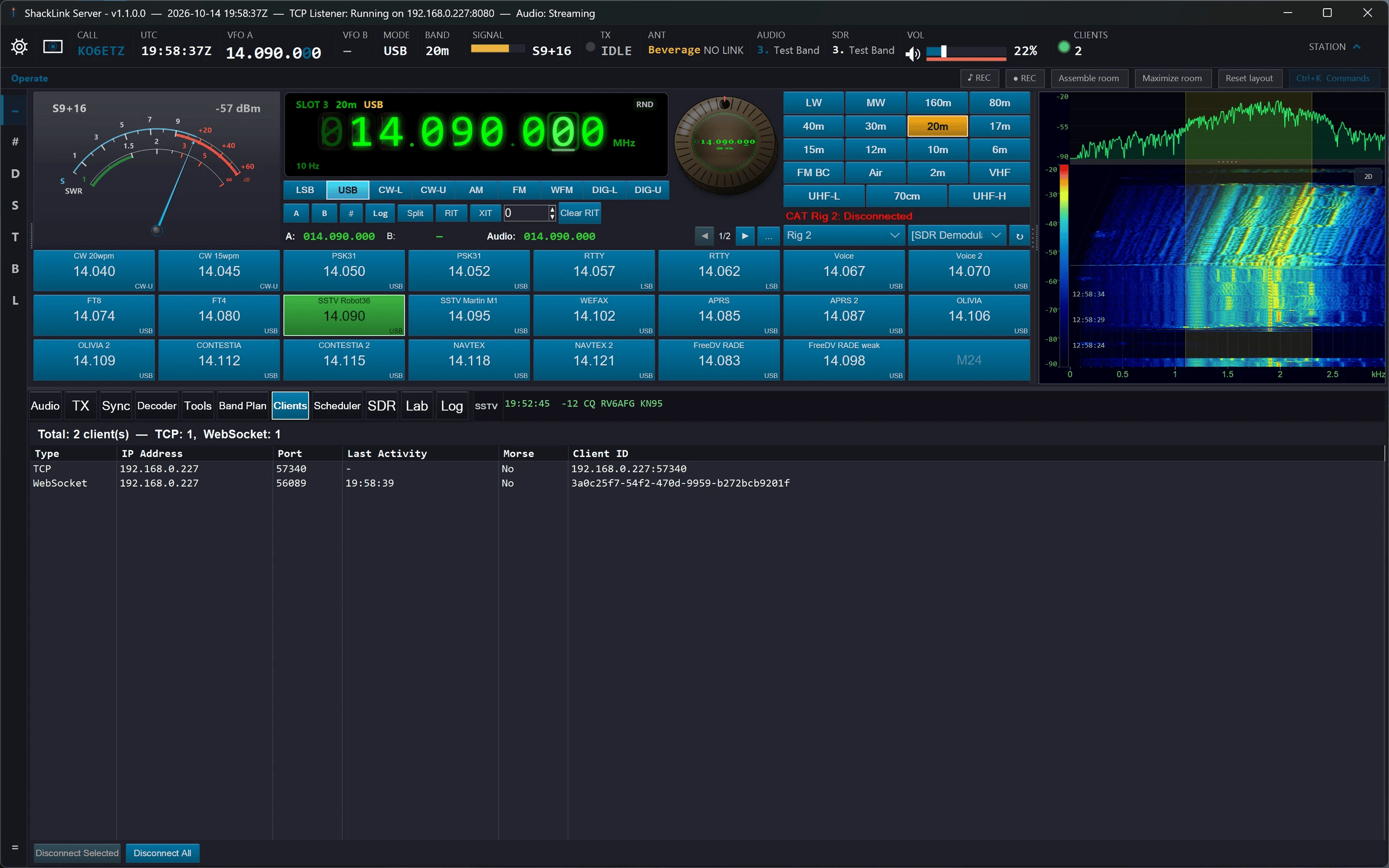
Client Management – Monitor and manage every connected client in real time
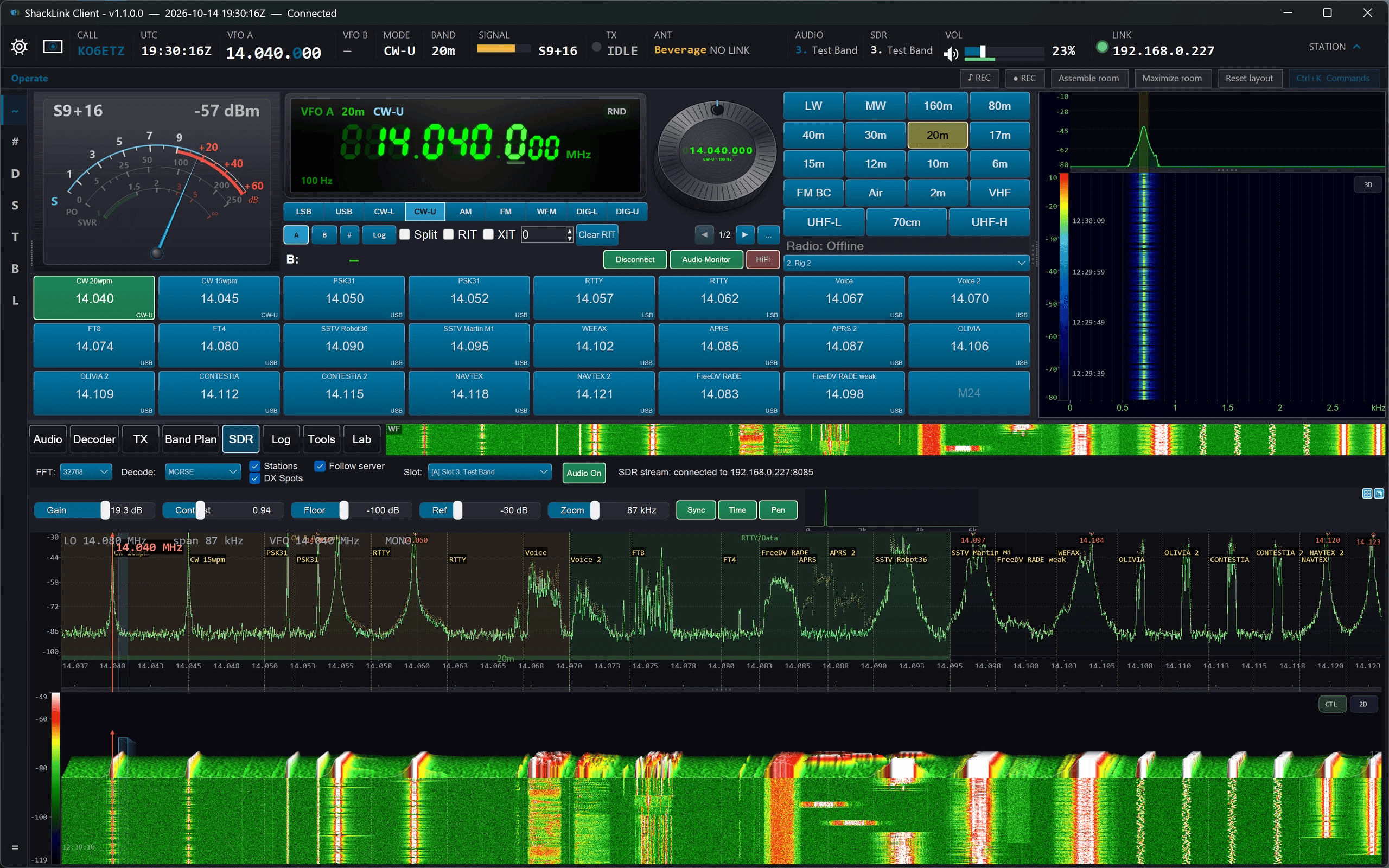
Desktop Client – Windows client with SDR panadapter and 3D waterfall
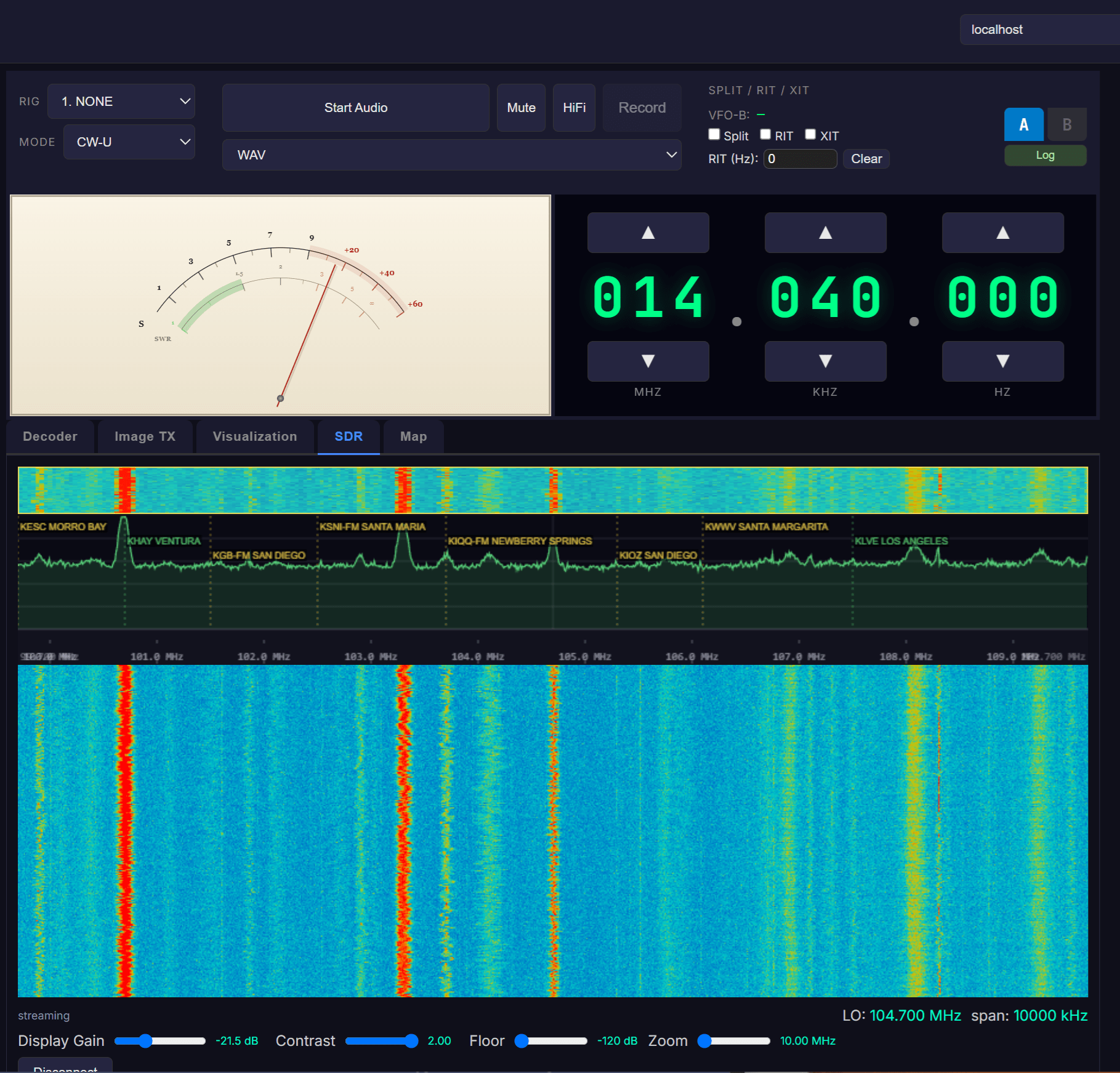
Web Client – Browser interface with frequency control and digital decoders

Home Assistant – Lovelace dashboard integration

Cross-Platform App – Windows, iOS, and Android with SDR panadapter and 3D waterfall
☝️ Touch Mode
A full-screen layout for a rugged touchscreen tablet: big keys, gloves welcome, nothing hidden behind a right-click.
New 2026-10. The normal window has far too much on it for a 12-inch screen in a vehicle. Touch mode is a second, separate layout for the same running server, designed for a Panasonic Toughbook-class tablet on a field table or a vehicle mount. Tap the touch cell on the flight strip, pick Touch Mode in the Start menu, or press Ctrl+K and type “touch”. The big DESKTOP key brings the normal window back exactly as you left it. Everything touch mode does goes through the same controls the normal window uses, so the two can never disagree.
- Sized for gloves. Every key is at least 12 mm on the glass. Sizes come from the panel’s real physical size, not from the Windows scaling setting, so the keys are the same size on any tablet.
- A palm cannot press anything. A key only acts when your finger is the only thing touching the screen. A hand resting on the glass blocks the keys until it lifts, so brace on the bezel.
- No hover and no right-click. Every function is a visible key, and every refusal is written on the page in words.
- The status strip along the top shows the frequency, the S-meter, the TX lamp and LISTENING TO, which picks the receiver you hear and nothing else.
- RADIO: a large frequency where tapping a digit sets the tuning step (1 Hz to 1 MHz), big DOWN / UP keys that repeat while held, a keypad with MHz and kHz enter keys, and twelve soft keys for band, mode, filter, AGC, noise blanker, noise reduction, notch, memories, split, RIT, volume (with squelch and NR level) and the keypad. One switch turns the page into a large waterfall.
- SPECTRUM: the panadapter. Tap to tune; drag with one finger to pan once zoomed in. ZOOM IN / ZOOM OUT keys replace pinching, PANADAPTER picks which receiver to show, and FOLLOW TUNING keeps what you hear in view.
- DIGITAL: the full FT8 / FT4 QSO console (decode list, wide graph, ANSWER, ENABLE TX, Tx1–Tx6, and a LOG IT / EDIT / DON’T LOG card), and CW, RTTY, PSK31 and Olivia with an audio waterfall, the decoded text and each decoder’s own settings keys. A MODES key reaches all twelve decoders. In CW, six macro keys send your macros.
- TRANSMIT: the transmit mode, the power in the transmitter’s own unit (with percentage presets on the radio), the transmitter’s state, TX monitor, your macros with the text each one sends, CW speed, and STOP.
- PTT: hold to talk, exactly like the TX tab’s push-to-talk. A quick tap does nothing, and the key says ON AIR, TEST, NOT KEYED or ENDED, and why it will not key in a mode other than voice.
- MORE: every tile of the Start menu on paged, finger-sized keys. A tile that opens a window steps touch mode aside first.
While touch mode is up it pauses the normal window’s own displays to save battery. On a narrow screen the photo panel can also be switched off from its right-click menu. The desktop client has the same five pages, working over the network.
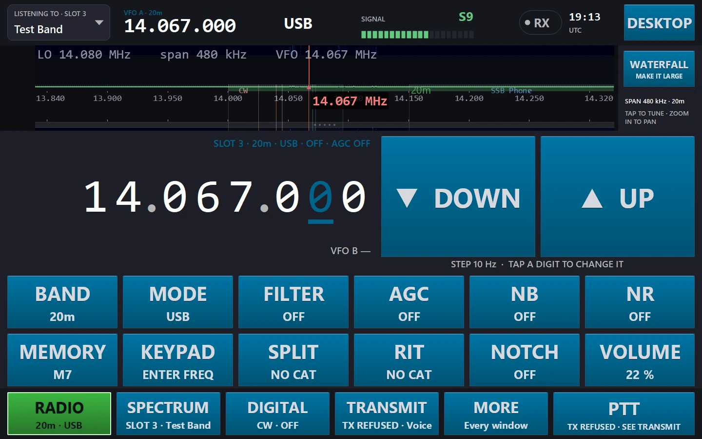
RADIO: the large frequency, DOWN / UP, and the twelve soft keys, each showing its current value
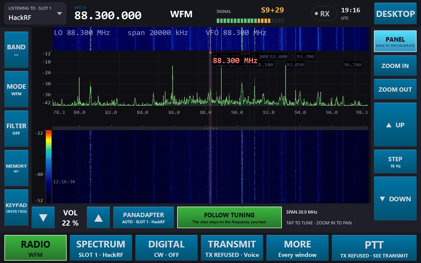
RADIO switched to its large waterfall, with ZOOM, UP / STEP / DOWN, VOLUME, PANADAPTER and FOLLOW TUNING
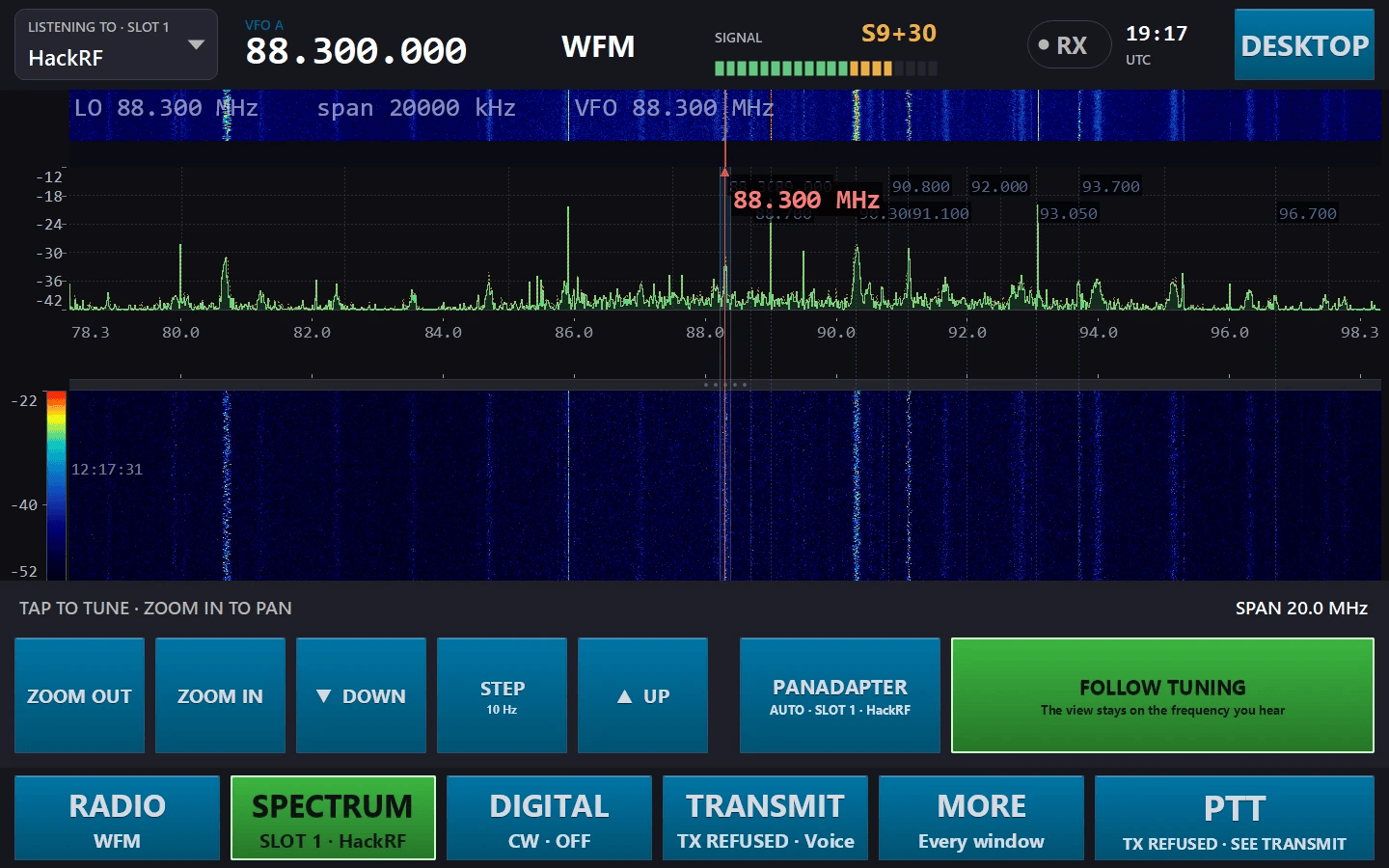
SPECTRUM: the panadapter, tap to tune, with zoom keys instead of pinching
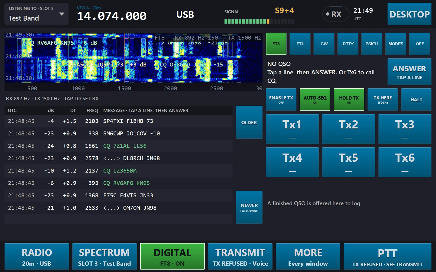
DIGITAL in FT8: the decode list, the wide graph and the QSO console on glass
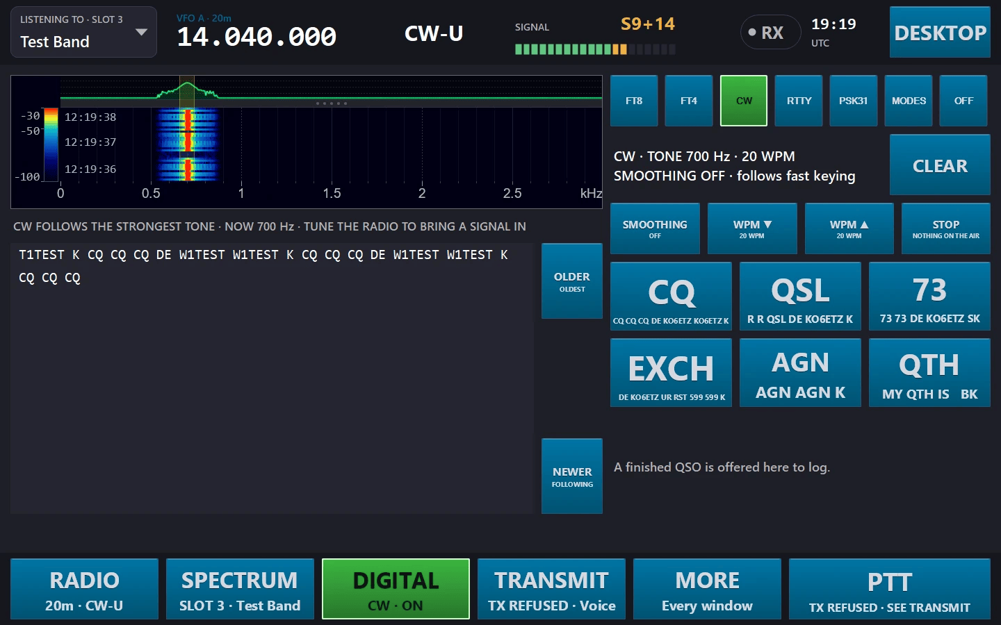
DIGITAL in CW: the audio waterfall, the decoded text, and six macro keys that send CW
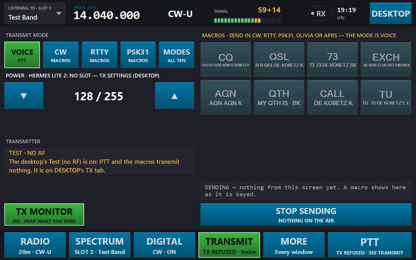
TRANSMIT: mode, power, the transmitter’s state, macros, CW speed and STOP
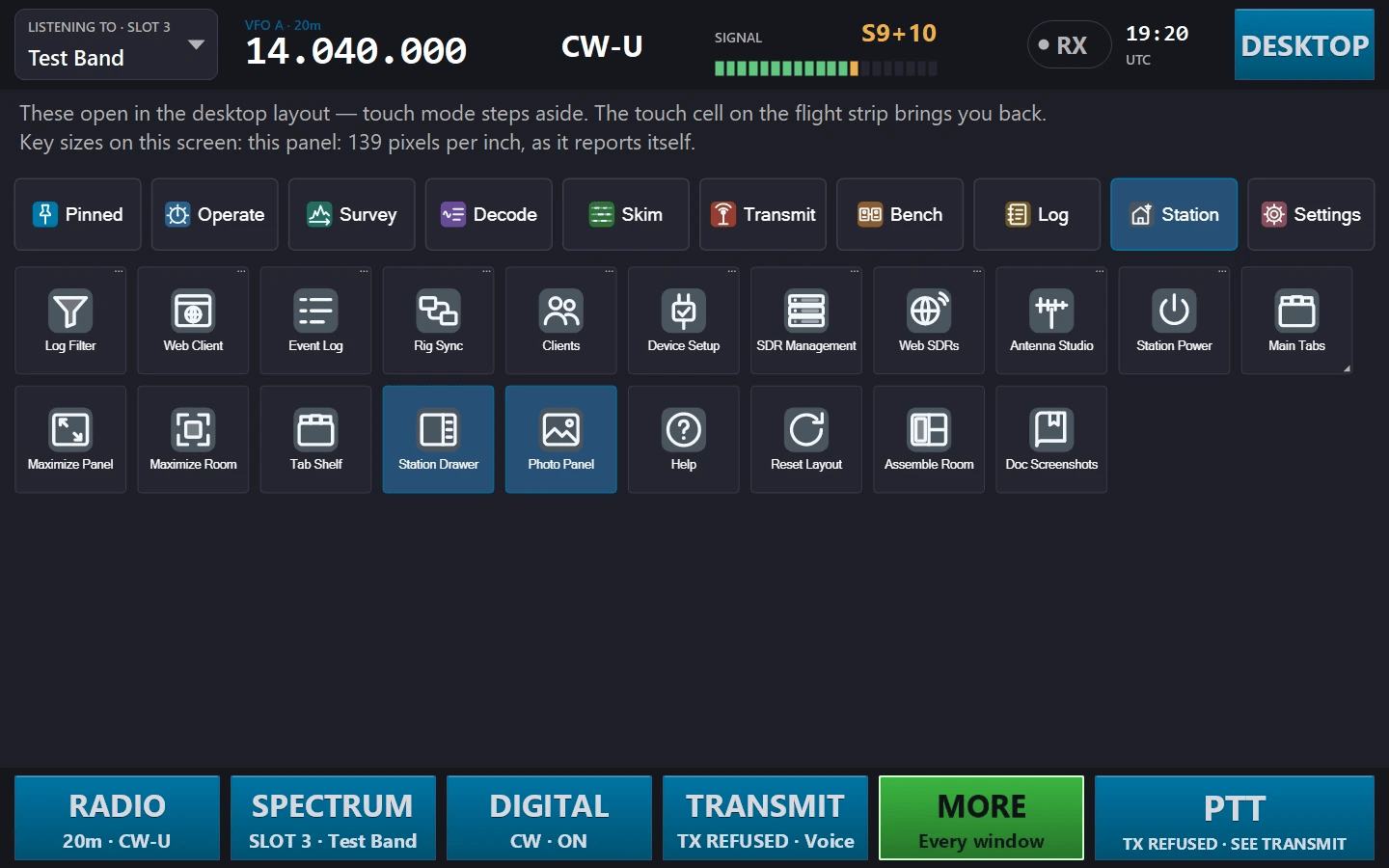
MORE: every Start menu tile on paged, finger-sized keys, grouped by category
👥 Client Management
Monitor and manage all connected clients from the server.
🌐 WebSocket Clients
View all connected web browsers and Home Assistant instances. See client IP addresses, connection time, and real-time status.
🕑 Auto-Refresh
Client list updates automatically every few seconds. New connections appear instantly, disconnected clients are removed.
🔒 Connection Control
Disconnect individual clients when needed. Useful for troubleshooting or managing server resources.
📊 Status Monitoring
Track audio streaming status and subscription state for each client. Identify which clients are actively receiving audio.
Accessing the Clients List
- Open the Clients tab, or the Clients tile on the Tools tab or in the Start menu
- Every connected client is listed with its type, IP address, port, last activity and client ID
- The list auto-refreshes to show real-time connection status
- Select a client and click Disconnect Selected, or Disconnect All
The connected-clients list with each client’s type, address and activity
💡 Client Types
WebSocket clients include web browsers accessing the built-in web client, Home Assistant Lovelace cards, the mobile app’s remote (unified) transport, and any custom integrations using the WebSocket API on the unified port 8084 (path /ws). When authentication is enabled, every connecting client must answer an HMAC-SHA-256 nonce challenge before any state or audio is delivered.
🛠 Installation
Get up and running in minutes with these simple steps.
Step 1: Install OmniRig v2.0 or later
OmniRig v2 is required for up to 4-rig support.
Download OmniRig v2.0 or later
Get it from hb9ryz.ch/omnirig
Configure Radio
Set COM port, baud rate, and select your radio model
Test Connection
Verify frequency updates when tuning your radio
Step 2: Install ShackLink Server
- Download the latest release from ditdots.com
- Extract all files to a folder (e.g.,
C:\ShackLink) - Run
ShackLinkServer.exe - When prompted by Windows Firewall, click Allow Access
📦 Required Files
Keep every file of the release together: the DLLs and the x64 subfolder must stay beside ShackLinkServer.exe. The install kit, when it is released, also offers optional parts: the web client, the help, the Signal ID engine, the USRP B2xx and PlutoSDR helper and the FreeDV decoder.
📁 Your own files live in your own folder
Since 2026-10 nothing ShackLink writes goes beside the program, so an installed server works as a normal Windows user. Your authentication settings, decoder plug-ins, diagnostic logs, and the files you supply yourself — rtl_tcp.exe for RTL-SDR dongles and ExtIO plug-in DLLs — all live under %LocalAppData%\ShackLink (for example %LocalAppData%\ShackLink\rtl_tcp and %LocalAppData%\ShackLink\ExtIO). Files already beside the program are still found.
Step 2b: Check your devices (Tools → Device Setup)
Open Device Setup from the Tools tab before your first SDR session. It checks this PC for every device ShackLink supports and tells you, device by device and in plain English, what is ready and what to do next. See Device Setup under Tools & Dashboards below.
Step 3: Configure Firewall (Station Settings → Server → Configure Firewall)
Allow incoming connections on these ports:
- 8080 – TCP radio control
- 8081 – TCP audio streaming and UDP auto-discovery
- 8082 – Voice TX uplink (LAN)
- 8084 – Unified HTTP + WebSocket (web client, HiFi MP3,
/ws), only port needed for remote access - 8085 – SDR spectrum stream (LAN)
Step 4: Connect Clients
Open a browser to http://[SERVER_IP]:8084 for web client, or install desktop/mobile client and enter server IP.
🎧 Audio Streaming
Setup
- Connect radio audio output to your sound card’s line input
- Pick that device as the Audio Input in the station drawer (an SDR slot can have its own input, set per slot in SDR Management)
- With an input chosen, streaming to clients starts automatically every time the server starts
🎙 Audio Format
Audio is streamed as 12kHz, 16-bit, mono PCM. This provides good quality while minimizing bandwidth (24 KB/sec).
HiFi MP3 Stream (192 kbps stereo)
The server simultaneously exposes a broadcast-quality MP3 stream at http://server:8084/hifi.mp3, served from the same unified port that hosts the web client and the WebSocket endpoint. One shared LAME encoder feeds every connected listener, no extra CPU per client. The encoder spins up automatically when the first client connects and idles when nobody’s listening.
- Works in any browser / VLC / mpv: paste the URL and go. No client install needed.
- ICY “Now Playing” metadata: clients that send
Icy-MetaData: 1receive the current rig / frequency / mode as a Shoutcast-style title, updated on every state broadcast. - Discovery-aware: the UDP broadcast on port 8081 advertises the server hostname, HiFi, SDR, WebSocket ports, and LAN auth requirement (
ShackLink Server;name=<hostname>;hifi=8084;sdr=8085;ws=8084;auth=<required|none>) so non-default configurations still auto-detect, clients can display servers by name, and native clients know up-front whether they need to authenticate. - When to prefer which stream: use 12 kHz PCM for low-latency work (CW, digital modes, hearing your own TX), HiFi for casual listening or voice reception where broadcast fidelity matters more than ~1 s buffer latency.
Volume Control
The Audio tab includes a system volume slider that controls the default audio output device level. The volume level and the audio monitor on/off state are persisted across sessions.
Demo Mode
Enable demo mode to generate synthetic Morse code audio for testing without a connected radio. Useful for development, demonstrations, and learning.
📡 SDR Panadapter
Real-time spectrum and waterfall display from an SDR receiver.
SDR tab: scope, navigator, and 2D waterfall

3D terrain waterfall: the 2D scope stays live above it

SDR Management: assign a source, audio input, and per-slot decode mode (the eight modes that can run per slot: CW, RTTY, PSK31, NAVTEX, APRS, Olivia, FT8, FT4) to each of 8 slots. The mode can also be set from the desktop, web and mobile clients, and every slot’s output is visible in the Slot Decoders console.
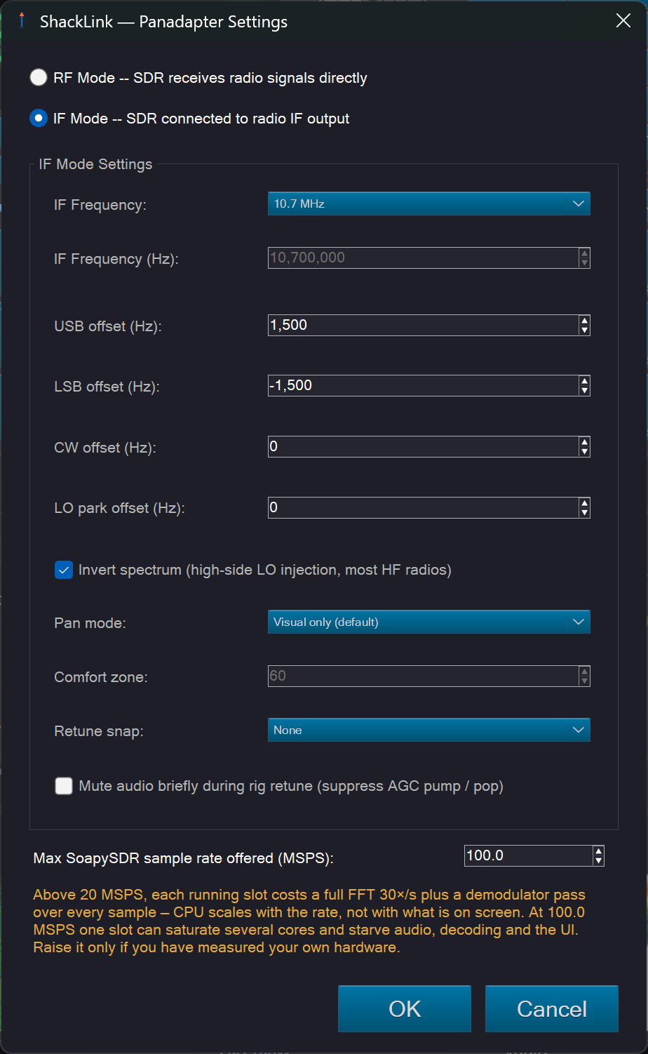
Panadapter Settings: RF mode or IF mode with sideband offsets and pan policy

Waterfall popout: independent 3D view for a second monitor

Phosphor spectrum persistence over the 3D terrain

The same view under a different palette

Monitor Channels: per-band channel banks with Name, PI, Level, Heard and Note columns, and the Find stations, Prune not heard and Fill grid buttons
Source Types
- ExtIO Plugin (DLL): Load any ExtIO-compatible plugin (Airspy, SDRplay, etc.). Put the plugin DLLs in
%LocalAppData%\ShackLink\ExtIO; a slot whose plugin you moved there still finds it. Device selection for adapters with multiple units is done through the plugin’s native GUI: click “Show Native GUI” after opening to access the plugin’s device picker. - RTL-SDR (via rtl_tcp): Drives dongles through rtl_tcp, a small open-source driver server; because librtlsdr/rtl_tcp are GPL they are not bundled. Download them once into
%LocalAppData%\ShackLink\rtl_tcp, or let Device Setup fetch the RTL-SDR Blog files from their publisher for you. Each local dongle is its own source entry; a network entry connects to a remote rtl_tcp instance (e.g. a dongle on a Raspberry Pi at the antenna). Direct sampling (HF on V3/V4 dongles) and bias-T are applied for real. Since 2026-10 a slot checks it opened the dongle it was bound to (USB order can change between the check and the open), and a dongle another program has open is listed by serial as in use by another program instead of vanishing from the list. - HackRF: In-process via libhackrf. RX + TX, half-duplex, 1 MHz – 6 GHz, up to 20 MHz bandwidth. WFM / NFM demodulation with polyphase FIR decimation for high sample rates.
- Hermes Lite 2: Ethernet SDR transceiver via HPSDR Protocol 1. Full-duplex RX + TX, 48–384 kHz sample rates, N2ADR LPF/HPF filter board auto-selection, SWR protection with auto-unkey, and temperature monitoring. Live frequency changes via C&C registers.
- Native Sound-Card I/Q: A regular sound card capturing baseband I/Q from an external IF tap or quadrature converter. Pick the input device, set the sample rate, off you go.
- Icom Native CI-V: Control an Icom CI-V radio (e.g. IC-705) directly, with no OmniRig required, and use its built-in spectrum scope as a first-class SDR slot. Works over USB serial or over the network (Wi-Fi) via Icom’s RS-BA1 protocol, which carries control, scope, RX audio, and TX voice. The scope reassembles from the radio’s CI-V waveform frames; center mode spans VFO ± span, fixed mode uses the configured edges.
- IQ File Playback Slot: Map a slot to a saved I/Q recording (a SigMF pair, a
.sigmfarchive, or a legacy.sliqfile) that loops forever, replaying captured spectrum like a virtual SDR. The LO is fixed at the recording’s center; click-to-tune moves the demod listen point, and FFT size stays adjustable. - Test Signal (synthetic): Sine + Gaussian noise generator for development and testing without hardware.
- Public web receivers: KiwiSDR / Web-888 and SpyServer stations (their I/Q, our demodulator), and (new 2026-09) OpenWebRX / OpenWebRX+ receivers, which demodulate on the receiver and send audio plus their band’s FFT — including the digital-voice modes DMR, D-STAR, YSF, NXDN, P25, M17 and TETRA with who-is-talking metadata. The receiver’s profile is the slot’s span; ShackLink never switches it under the receiver’s other listeners.
- SoapySDR (new 2026-08): Airspy, Airspy HF+, LimeSDR, ADALM-Pluto, bladeRF, netSDR, and any radio on another machine through SoapyRemote — with the runtime installed separately (radioconda), receive only. Radios ShackLink already drives natively, and GPL-licensed modules, are kept out.
- USRP B210 and PlutoSDR-class boards (new 2026-09): through a separately installed companion program (UHD is GPL, so it never loads into ShackLink). Each board is a radio slot for its whole span plus up to seven narrow sub-receivers inside it; a B210’s second receive channel is a radio slot of its own, and (new 2026-10) so is a Pluto’s second input, RX2A, on boards that report one, with every input named as the board names it; a USRP radio slot is a no-hop wide-scan source; both can transmit through the normal interlocks. Still being commissioned on hardware.
Converters, transverters and LNBs (new 2026-09-15): any slot with a fixed-LO converter in front of it — a Ham It Up, a SpyVerter, a 2 m / 70 cm / microwave transverter, a Ku- or C-band LNB — is configured once with its offset (presets included) and from then on everything reads real RF, up to 300 GHz. An inverting LNB’s mirrored spectrum is put right at the source, a documented passband refuses tunes outside it, and transmit through a converter needs a declared drive cap.
Sources are assigned to slots from the SDR Management dialog (there is no longer a single source dropdown). Most drivers run in-process; only ExtIO plugins go through the 32-bit broker subprocess; RTL-SDR runs through the separate, user-supplied rtl_tcp process instead. Since 2026-10 a radio another slot is already using stays in the list, marked with the slot that holds it; picking it asks whether to move it, and moves it only if you say yes.
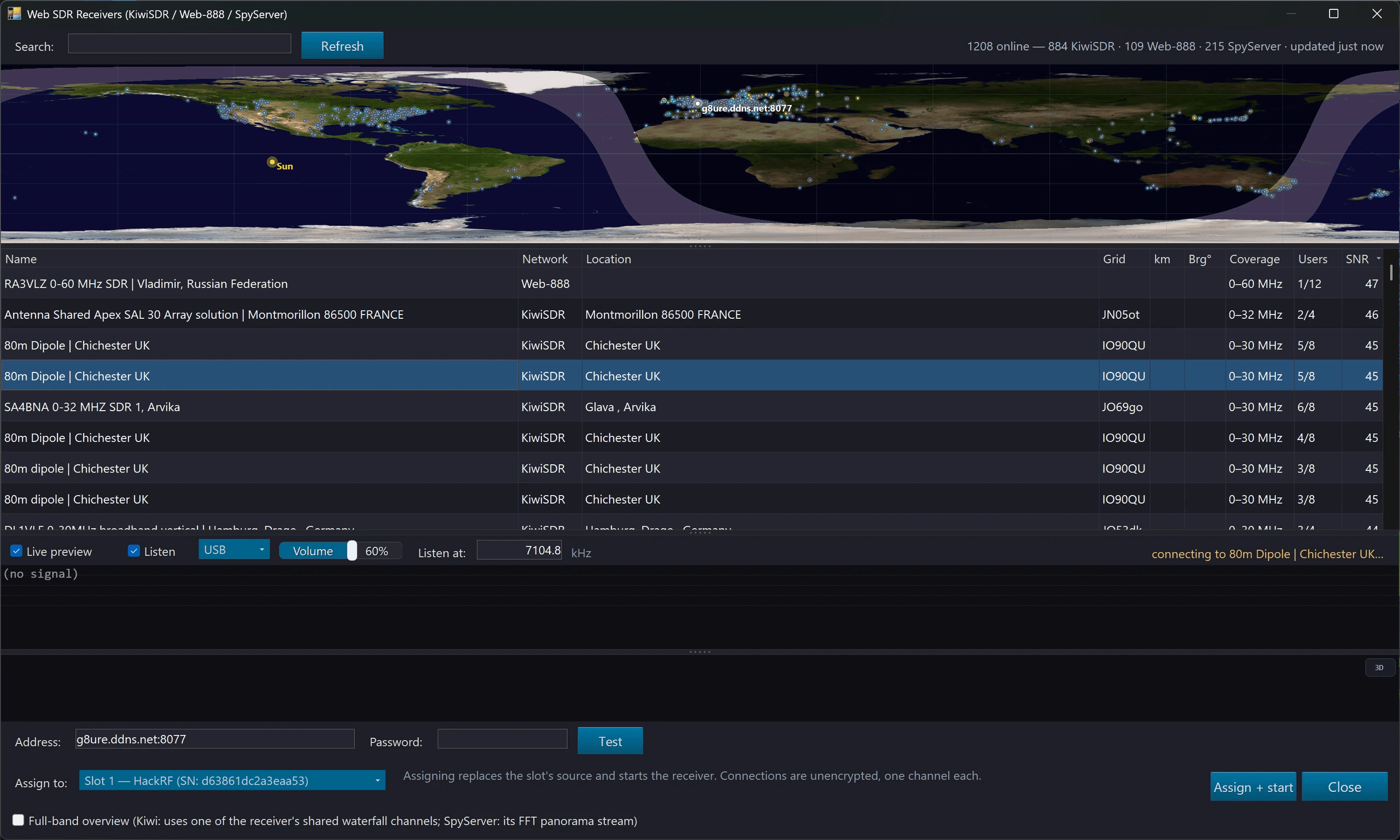
Web receiver browser: the KiwiSDR, Web-888 and Airspy directories in one sortable list over a zoomable world map, with a live spectrum, waterfall and audio preview before you give a slot to a receiver
FFT Size
The FFT combo on the SDR tab controls frequency resolution (4096 / 8192 / 16384 / 32768). Larger FFT = sharper waterfall when zoomed, at the cost of more CPU. Default is 16384. Changes take effect immediately and persist per-device.
Display Features
- Embedded + Popout: Scope + waterfall on the SDR tab, plus a “Popout Spectrum” button for a resizable window
- Auto-center: The waterfall automatically follows rig frequency changes for all SDR sources (HackRF, Hermes Lite 2, Sound Card I/Q, ExtIO/Broker), keeping the current signal centered on the display
- Click-to-tune: Click on the waterfall to set the rig frequency (or the SDR LO in RF mode)
- Drag-to-pan: Drag the spectrum or the frequency strip to slide the band; in IF mode the policy follows the server’s Pan mode setting
- Memory markers: Toggle “Show memory markers” to overlay stored memory frequencies on the spectrum
- DX spot markers, Live DX cluster spots drawn on the waterfall with callsign labels, color-coded by age
- Broadcast station markers: Known broadcast station frequencies overlaid on the waterfall with station name labels
- Gain / Contrast / dB floor: Adjustable via sliders on the popout toolbar
- Per-client zoom, Each connected client requests its own zoom span; a navigator overview channel shows where you are in the full band
- Navigator overview: A miniature full-band view showing the current zoom window position, enabling quick orientation within the band
- Phosphor spectrum: Persistence-overlay mode that accumulates spectrum traces over time, visualizing signal density and intermittent signals
- Phosphor histogram (experimental): An optional GQRX-style density/histogram color mode for the phosphor overlay (coarse cells + IIR smoothing), alongside the existing amplitude-hue and Gaussian-spread modes. Still an A/B experiment pending a verdict
- Waterfall view — three modes, not two: flat 2D, a full-pane 3D perspective terrain of spectrum history, and Split, which puts the terrain on the top half and the flat scroll underneath, joined on one shared instant: both show now at the seam, and history runs away from it in both directions. Right-click → Waterfall View, or the corner button, remembered per slot. Parallel projection is now the default for the full-pane view too, with the orbit camera one click away — under perspective only the centre column runs straight up, so edge ridges lean opposite ways, which reads as depth on its own and as a fault line the moment a flat waterfall sits underneath. GPU-accelerated via OpenGL with a CPU fallback that says so on a badge; heights and colours reuse the 2D waterfall palette for exact parity. All three modes ship on five surfaces — the SDR pane, the Lab spectrogram, the audio visualisation, mobile, and the web client
- Palettes: thirteen named waterfall gradients (two of them light) and twelve spectrum ones, one name-keyed set each, identical across the server, the desktop client, the Lab, Multiband, mobile and the browser. Both are picked from a grid of little rendered waterfalls rather than a list of names, and every tile renders the same synthetic frame so the tiles differ only in the palette. The spectrum set opens with a Solid (single colour) sentinel — the single-hue trace the SDR has always drawn
- Waterfall Ref (max-level): A Ref slider sets the top of the waterfall color scale (default 0 dBFS) so strong signals actually reach the top of the palette; gain headroom now runs to +60. Mirrored on the Lab spectrogram
- Zoom FFT: Server-side NCO + decimation zoom providing high-resolution narrow-band views without increasing overall FFT size
- AGC speed / IF gain / Filter presets: SDR receiver controls for AGC attack/decay speed, IF gain adjustment, and predefined filter bandwidth presets
- Multi-SDR slots, Up to 8 devices simultaneously, each in its own slot with independent LO, FFT size, demod settings, and optional per-slot decoder. Slot selector appears in all clients when multiple devices are active. One slot at a time feeds the audio output.
- Multiple identical devices: Run several of the same kind at once (multiple HackRF, SDRplay, Hermes Lite 2, or RTL-SDR units), each bound to its own slot by serial number (MAC address for Hermes Lite 2) so it keeps pointing at the same physical unit across USB re-ordering.
- SDRplay two-stage gain: RSP devices expose both gain stages on the panel: the IF Gain combo (0–59 dB) plus an RF LNA state combo (0 = max front-end gain; dB per state is band/model dependent: the SDR log’s “Gain report” line shows the real figures). Max sensitivity = IF 59 dB + LNA 0. Hardware AGC runs a 50 Hz loop at a −30 dBFS setpoint; switching AGC off returns to the last manual gain, and picking a manual gain switches AGC off. All of it persists per device and restores at slot start.
- Automatic recovery: A slot whose device dies or whose stream stalls restarts itself automatically (RTL, HackRF, Hermes Lite 2, SDRplay); the SDRplay API service self-heals if it stops or wedges; and streaming SDR slots restart automatically after the PC wakes from sleep.
Auto-Identify Signals (AI Recognition)
A neural-network classifier can scan the panadapter continuously and label every signal with its recognized mode. Right-click the spectrum display → Auto-Identify Signals to start a background scan of the selected slot; each confidently identified signal gets a small colour-coded chip centred on its carrier, with a guide line through the scope and waterfall.
- Colour-coded by family: CW, RTTY/FSK, PSK, MFSK, FT8/FT4, image (SSTV/WEFAX), packet/APRS, and voice each get a distinct chip colour
- Hover card: resting on a chip shows the top candidate modes with confidence, plus the measured frequency, bandwidth, SNR, and any decoder cross-check result
- Confident only: noise, unknown signals, and cross-check mismatches are hidden; a chip clears automatically the moment its signal goes off the air, and identified signals scrolled out of view are summarised by an edge arrow + count
- Show Signal Labels: a separate right-click toggle hides / shows the chips locally without stopping the scan
- Server-authoritative: the scan runs on the server and the chips are broadcast to the desktop client, which renders them identically. The classifier recognizes the modes in the installed model package; a signal outside that set is left unlabelled rather than guessed
- Scans you cannot see (new 2026-10): a scan left running on another slot is named in every slot’s right-click menu, with a Stop beside it, so it can no longer use CPU unnoticed
Auto-Identify needs raw I/Q, so it is available on IQ-capable sources (ExtIO/broker, RTL-SDR, HackRF, Hermes Lite 2, SDRplay, sound-card I/Q, and the synthetic test band); Icom scope slots and IQ-file playback are excluded, and it is refused while a slot is in IF-panadapter mode. A one-shot Identify Signal right-click option identifies a single signal (with optional decoder confirmation) even when the continuous scan is off.
RDS (Radio Data System)
RDS auto-activates whenever the SDR demodulator is in WFM: it is not a decode mode you select. It decodes the 57 kHz subcarrier for the station name (PS), programme identification (PI), RadioText, programme type, clock time, and traffic/network data.
It surfaces in the same idiom as the Auto-Identify chips above: a teal chip at the tuning marker on the SDR spectrum display reading “RDS <station name>”, dim until sync, with the full detail (PI, PTY, RadioText, clock, ECC / language, TMC / EON) on the hover card. The chip appears on the embedded SDR tab, on slot popouts, and in the SDR grid cells.
Station Slice and the SDR Grid
Two more ways to look at the receivers, both on the Tools tab and in the Start menu, and both on the desktop client too. Station Slice is an SDR view that stays zoomed on the station you are listening to — the passband plus a margin — and re-frames itself as the mode, filter or frequency changes, with its resolution written on its header. The SDR Grid is one window showing every running slot at once, each cell a full spectrum and waterfall with its own right-click menu, re-flowing as slots start and stop.
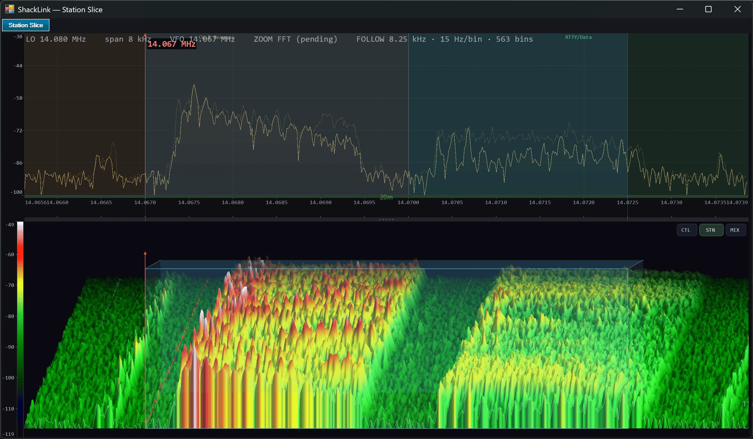
Station Slice: always zoomed on the station you hear
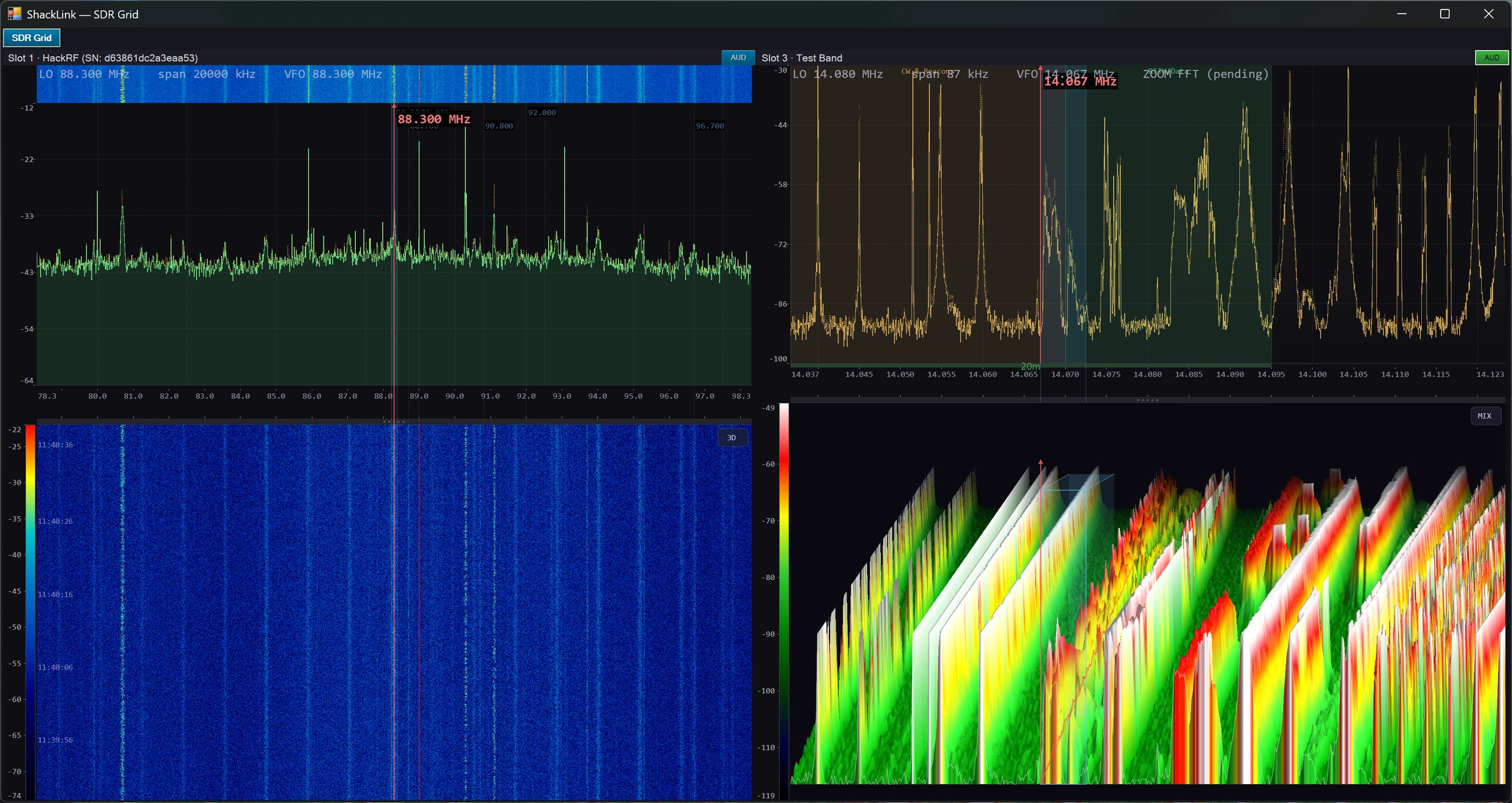
SDR Grid: every running slot in one window
Find Stations (Monitor Channels)
New 2026-10. Find stations works like a car radio’s autostore. Press it in the Monitor Channels window (the channel-count button on the SDR tab), or right-click a band on the SDR tab or a slot popout. It sweeps the band the receiver is on — even a band wider than the receiver can see at once — and stores every station it finds in a bank named after the band (FM BC, MW, and so on). Double-click a row to tune it.
- FM stations are named from their RDS. With the receiver in WFM and RDS on, each station found is visited briefly after the sweep and named from its RDS station name, and the receiver goes back to exactly where it was. If naming cannot run, it says why in words and the stations are stored unnamed. Two stations sending the same RDS identity are flagged as a possible image, never removed.
- A re-scan merges. New stations are added, the names you typed are kept, and a station not heard this time is marked, not deleted. Prune not heard is a separate, deliberate press.
- Fill grid is the old range fill (one channel every step, on the air or not), right for airband or repeaters; it now asks before it replaces a bank.
- It uses the Wideband Scan engine, so it will not start while a wideband scan is running, but the Wideband Scan window can stay open. Server only for now.
- Status: the first run on the air missed the weakest FM stations. The log now lists every signal the scan heard but left out, with its level, so the next runs can tell “never heard” from “heard and dropped”. RDS naming has not yet met a real radio.

Monitor Channels after Find stations on the FM broadcast band: each station it found, with its RDS name and PI code where one was heard, its level and when it was last heard
TETRA Receiver
New 2026-10. TETRA is the digital trunked radio used by many public-safety and utility networks. Set an SDR slot’s demodulator to TETRA and ShackLink’s own receiver decodes the cell it hears. Any local slot that delivers at least 36 kHz of I/Q can do it (not an Icom scope slot); an OpenWebRX receiver decodes TETRA itself and its slot shows that receiver’s own lines.
- The cell: network and cell identity, colour code, carrier frequency, whether the cell is encrypted, and its neighbouring cells.
- The four timeslots: what each one carries right now — control channel, a call, or nothing — and who is talking to which group.
- A call log and a short-data log: one row per transmission, and each short data message with its text when it was sent in clear.
- Voice: the first clear call plays on the slot’s audio, so every client listening to that slot hears it. Click a timeslot to listen to only that one. Encrypted calls are reported as encrypted and never opened.
- The codec tables are yours to import. ShackLink contains nothing written by ETSI. To hear voice, import ETSI’s own speech-codec archive once: SDR Management, right-click a slot’s Source cell, TETRA voice codebooks…. Everything else works without it.
The TETRA panel (Tools tab, or the Start menu’s Decode category) shows one band per TETRA slot with a lock lamp, the cell line and the four timeslots, over the call and short-data logs. The desktop client shows the same panel and can pin a timeslot too. Status: it decodes a real off-air recording of a clear cell, voice included, and matches ETSI’s own decoder on it; it has not yet been run against a live cell in the app.
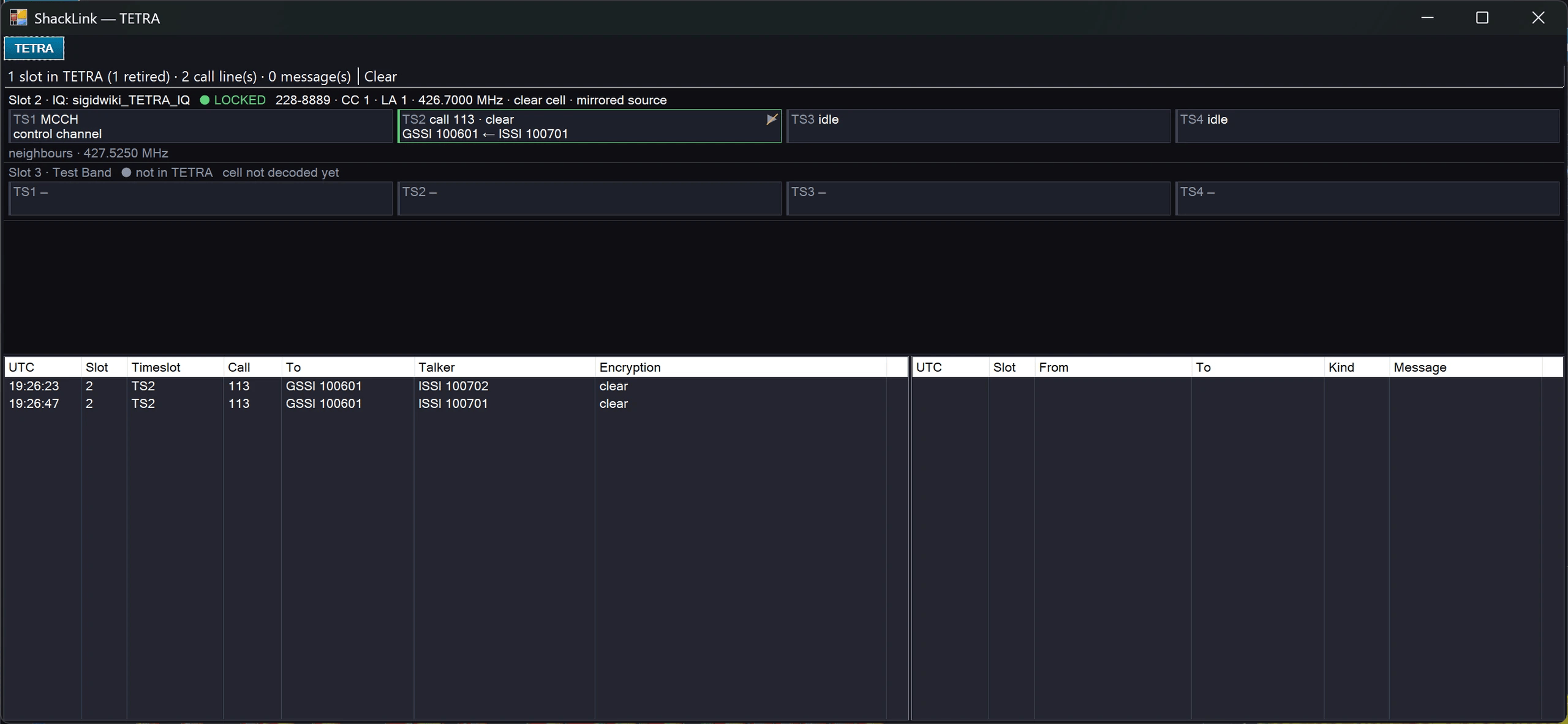
The TETRA panel: the cell, its four timeslots and the call in progress, over the call and short-data logs
Architecture
ExtIO-based SDR sources use a 32-bit broker subprocess (ShackLinkSdrHost.exe) that loads the plugin, captures IQ data into a shared memory-mapped ring buffer. The server (64-bit) reads the ring, runs a windowed complex FFT, and produces dB-scaled spectrum lines at 30 fps. HackRF, Hermes Lite 2, and Sound Card I/Q run in-process (no broker), feeding IQ samples directly into the same FFT pipeline. Lines fan out to: the embedded display, the popout window, TCP 8085 stream (desktop client), and WebSocket binary frames (web/mobile/HA clients).
IQ Recording (SigMF)
Record live SDR I/Q to SigMF (the open Signal Metadata Format): either a SigMF meta+data pair or a single .sigmf tar archive, for later analysis or replay. The archive writer transcodes between sample formats (ci16, ci32, cf64, cu16). Zoomed (NCO + decimated) recordings are captured correctly and in real time. The legacy .sliq writer has been retired, but old .sliq files still play back. A recording can be replayed one-shot, or mapped to a looping IQ File Playback Slot (see Source Types above).
Per-Slot Audio Input
Each SDR slot can carry its own audio input device (an “Audio In” column per slot row in the SDR Management dialog) instead of one global input, so switching between, say, a USB-rig slot and an SDR slot no longer grabs the wrong sound device. Leave it empty to inherit the global Audio-tab device; SDR slots default to the SDR demodulator. The setting follows the audio-active slot (the one you hear).
🔬 Lab Measurements (RF Workstation)
Professional multi-trace spectrum analysis built on up to 8 simultaneous SDR sources. Available on both the server and the desktop client.

Lab tab: multi-trace analyzer, Traces/Markers grid, and spectrogram

3D spectrogram terrain

Peak markers on the selected trace

Spectral CCDF panel below the analyzer

Stitch segments: the lane-strip editor composes a gap-free multi-band view

The same composed view in the independent Lab popout

Palette variation
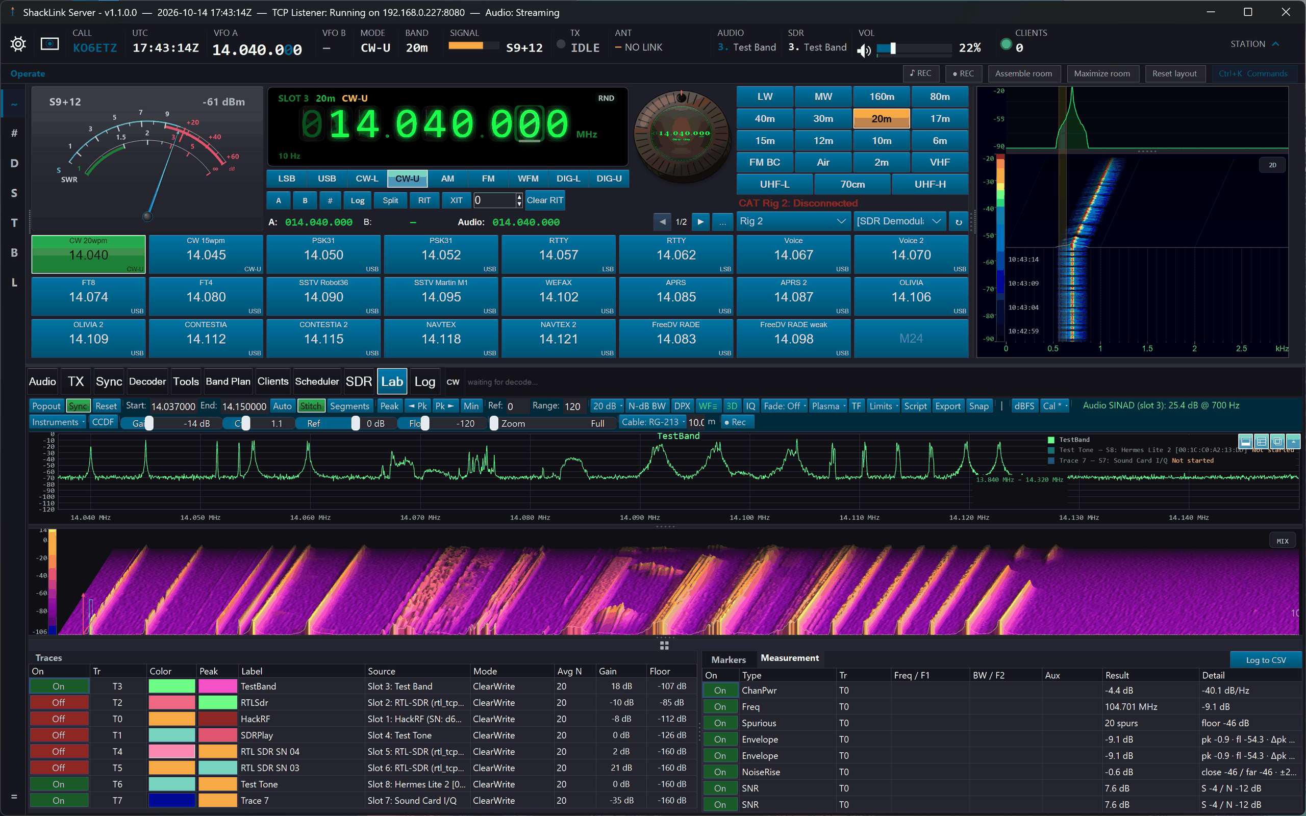
Palette variation

Palette variation
Multi-Trace Overlay (8 Traces)
The Lab tab provides a SkiaSharp-rendered spectrum display with up to 8 independent traces, each bindable to a different SDR slot. Per-trace controls include:
- Trace modes: ClearWrite (live), MaxHold (peak envelope), MinHold (noise floor), Average (configurable N), RMS
- Math traces: A+B and A−B operations between any two traces for comparison and delta measurements
- Per-trace gain offset (−60 to +60 dB) and noise floor (−160 to −20 dB) via slider columns in the Traces grid
- Color customization: independent trace color and peak-hold color per trace, chosen via color picker
Zoom & Stitched Multi-Band View
The mouse wheel zooms at the cursor on both the analyzer and the waterfall (Ctrl+wheel = gain, Ctrl+Shift+wheel = floor), backed by a zoom history (Zoom Back via right-click or the mouse’s back button), a Zoom Out ×2 action, a log-scale toolbar Zoom slider, and draggable navigator edge grips. Stitch mode deletes the empty gaps between disjoint SDR bands and splices the covered ranges into one continuous axis: a 40 m slice directly beside a 20 m slice.
- Stitch segments (kept ranges): each trace can contribute just a chosen slice of its span to the stitched view, so you compose exactly the multi-band picture you want (e.g. only the FT8 windows of three bands, side by side).
- Segment lane editor: the Segments toolbar toggle opens one lane per visible SDR trace: a live mini-spectrum of the slot’s full span with the kept range as a draggable band (drag edges to resize, body to move, empty space to draw, double-click for full span). The plot re-stitches live while you drag.
- Quick actions: or simply zoom into a slice and right-click → Stitch Segment ▸ Keep Current View.
- Honest by design: segments are render-side only (markers, measurements, and exports still read the full trace at real frequencies), kept ranges survive retunes (they ghost while the slot is away and re-apply when it returns), and no LOs move, so it works on rig-tracking and IF-locked slots too.
Marker System (8 Markers)
Up to 8 simultaneous markers with real-time frequency and amplitude readout:
- Normal: frequency and amplitude at the marker position
- Delta: frequency and amplitude difference between two markers
- Band Power: integrated power within a specified bandwidth
- Noise: noise density in dBFS/Hz
- Peak search / min search: jump to the highest or lowest point, navigate left/right between peaks
- N-dB bandwidth: find the −3/6/10/20/40/60 dB bandwidth around the current marker
The spectrum right-click menu adds Place Marker Here (drop a marker at the clicked frequency) and Clear All Markers (remove every placed marker and clear the marker grid in one action).
Automated Measurements
An eight-row Measurements grid (a label tab beside Markers) computes a chosen measurement per trace on every sweep, with blank-for-auto parameters and live Result/Detail columns; a quick readout also appears in the toolbar. Available measurements:
Channel Power
Total power within a defined channel bandwidth.
OBW
Occupied bandwidth containing 99% of signal power.
ACPR
Adjacent channel power ratio for transmitter testing.
SNR
Signal-to-noise ratio measurement.
Harmonics / THD
Harmonic distortion analysis with individual harmonic levels.
IMD / IP3
Intermodulation distortion and third-order intercept point.
CFO
Carrier frequency offset vs a reference, in Hz and ppm.
Occupancy
Percent of a band above the noise floor, averaged over a time window.
Duty Cycle
Percent of time a channel is keyed (active) over a time window.
Envelope
Peak / current / floor at a frequency, held across sweeps.
Image Rejection
I/Q image-rejection ratio: a signal versus its mirror across the receiver’s DC, in dBc.
Noise-Floor Rise
Close-in noise floor near a strong carrier versus the far floor: a reciprocal-mixing proxy.
Spurious vs SM.329
Spurs reported as dBc below the carrier against a simplified ITU-R SM.329 mask, with a PASS/FAIL count.
Spectral Flatness
Spectral flatness (Wiener entropy) over a band, with passband ripple.
A Log to CSV toggle on the Measurements tab appends every enabled row to %LocalAppData%\ShackLink\Lab\measurements.csv about once per second for trend analysis. Readings are relative (dB/dBFS/dBc/%/Hz) by default.
Amplitude calibration (approximate dBm). There is no traceable power calibration, so the Lab is relative (dBFS) by default. You can assert an approximate reference per SDR slot: set the amplitude unit to dBm, then type a per-slot offset or use the Cal drop-down’s “Set from marker” helper (offset = known dBm − marker dBFS). Absolute readouts then show dBm*: the * marks it user-asserted, not traceable. Relative metrics are unaffected. Any gain change on the slot (MGC / LNA / AGC, conservatively IF gain) marks the calibration stale and reverts it to dBFS, so a stale offset never silently lies; the server also broadcasts a per-slot gain-change pulse so remote desktop clients invalidate their own calibration.
Display Modes
- DPX persistence: temporal density display showing signal persistence over time. Color palettes (unified with the SDR tab): Classic (blue), Classic (green), CoolWarm, Viridis, Plasma, Inferno, Grayscale, Neon (cyan), Signal (teal), Semaphore, Rainbow, Paper (light), Blueprint (light)
- Spectrogram waterfall: time-frequency display with gain, contrast, floor, and speed controls. Synchronized frequency axis with the main spectrum. Toggles to a 3D perspective terrain view of the spectrogram history (GPU-accelerated, with a silent CPU fallback)
- Spectral CCDF: complementary cumulative distribution of spectrum-bin amplitude vs the mean (frequency-domain spectral peak-to-mean, not time-domain PAPR / crest factor)
- PSK constellation + EVM/MER: live I/Q scatter of recovered PSK31 symbols (2 points BPSK-31, 4 QPSK-31) with persistence, ideal-point overlay, lock indicator, and a true modulation-quality readout (Error Vector Magnitude %, Modulation Error Ratio dB). PSK31-only; honestly shows “—” when not locked. Computed server-side and streamed to the desktop client. A VSA summary adds peak EVM, a magnitude/phase-error split, residual carrier frequency error (after AFC), and I/Q offset, with a 60-second EVM trend
- Audio SINAD: true signal-to-noise-and-distortion ratio of a steady tone in the demodulated audio of the active SDR slot (a CW/SSB beat-note, an AM/FM tone, or a test tone). Measured from the actual demod audio, not the spectrum; a ratio, so no calibration needed; honestly shows “—” with no tone. Computed server-side and broadcast to the desktop client
Instruments (Dedicated Instrument Windows)
An Instruments toolbar dropdown opens twelve focused, single-purpose windows, each running alongside the analyzer, modeled on professional spectrum-analyzer application firmware. Six look at whatever arrives at the receiver; six transmit something known so there is a controlled signal worth measuring. The transmitting six are server-only (only the server has a transmitter), as are the Zero-Span Scope and the recorder; everything else also runs on the desktop client.
A rule that runs through all of them: they never invent a number. Where an instrument cannot honestly measure it shows an em dash, a named warning badge, or refuses to start, and until the level-calibration wizard has been run, every transmitting instrument states its level in dBFS and says why rather than printing a dBm figure it cannot support.
Signal Generator (server)
Eleven waveforms: carrier, two-tone, multitone comb, band-limited noise, pulsed burst, square, sinc, pulse train, gaussian pulse, chirp, arbitrary from WAV/CSV, each optionally AM / DSB / FM modulated, picked from grids of drawn pictures rather than dropdowns. Rehearse renders it silently into the Test Tone slot first, exactly (not approximately) as it will go out, so it appears on every client’s waterfall with nothing on the antenna.
TX Calibration (server)
Two wizards in one bench session. Level calibration builds the transmitter’s gain × frequency table: a loopback through a known pad gives the curve’s shape, your power meter supplies the one absolute anchor, and until that anchor exists everything honestly reads dBFS. Source characterization measures the transmitter’s own harmonics, spurs and IMD3, so later measurements can say “source-limited” instead of quietly reporting the generator.
TX Health Check (server)
The purity bench: two-tone IMD, CW keying, ALC overshoot and PTT timing, harmonics and spurious, modulation quality, and composite noise, six measurements onto one dated report card, scored against the ARRL Clean Signal Initiative masks. A reading within 6 dB of the analyzer’s own noise comes back as the floor with a “≤” in front of it, never as a result.
SWR Sweep (server)
Sweeps SWR across a span using the radio’s own bridge: a resonance finder rather than an impedance instrument. A radio whose meter curve is not in this build still sweeps in raw meter units and declines to claim a VSWR number, because the dip’s position does not need the curve and the magnitude does.
WSPR Beacon (server)
Beacons WSPR on the bands you pick and collects who heard you from three independent spot feeds, drawn as paths out of your station on the greyline map. A reception seen by two feeds is marked corroborated and carries both; where they disagree the spread stays beside the figure. The transmitted power is always your declaration; calibration only caps a claim above the radio’s measured maximum.
IQ Replay (server)
Transmits a recorded or synthesized I/Q scene out of the HackRF or Hermes Lite 2. The rate conversion is the honest core: exact ratios where the arithmetic allows one, a stated residual in ppm where it does not, and a refusal past 1000 ppm, because a scene at the wrong rate is a signal at the wrong bandwidth and looks entirely plausible on a waterfall.
Modulation Analyzer
AM depth / FM deviation (peak & RMS) / carrier offset / modulation rate of the slot you are hearing, on an analog needle face. Tapped from the demodulator, not the spectrum; AM/FM only; honest “—” with no carrier. (FSW-K7-style.)
Mask Trigger
Arm a limit mask over a trace; a violation fires a black-box pre/post I/Q capture to SigMF, a spectrum snapshot, and webhooks, with an event list and slot timeline. (Tek RSA FMT-style.) The client is a view-only console.
Zero-Span Scope (server)
An RF oscilloscope: envelope vs time of an IQ slot with scope triggering (Auto / Normal / Single / Free-run) and automatic burst measurements: rise/fall, width, period, duty, overshoot, on/off ratio.
Phase Noise
Carrier-tracked SSB phase noise L(f) dBc/Hz vs log offset: ENBW-correct, spur-excluded, window-skirt-masked, with a decade table (10 Hz–1 MHz), integrated jitter, and reference compare. (FSW-K40-style.)
Noise Figure
Guided Y-factor NF with a calibrated noise head: system NF (Mode A) or DUT NF + gain via Friis (Mode B), NF(f)/gain(f) curves, ENR head profiles, and gain-change voiding. (NFA / FSW-K30-style.)
3-D Spectrogram
New 2026-10. A block of sweeps drawn as a 3-D surface you can turn all the way round, zoom and pan, with labelled axes and a colour bar. Click it to pick a real frequency and a real moment, and that sweep’s spectrum and history are drawn over the surface. Capture a few seconds, or run Live as a rolling window, from a live SDR slot or a Lab trace — and on the server, from a stretch of a SigMF recording. AUTO fits the colours to the data.
Video Recording (server)
A ● Rec button records the Lab display (or the whole window) + system audio to MP4 in Videos\ShackLink, with selectable scope and 30/60 fps. Also on the SDR and Lab popout windows.
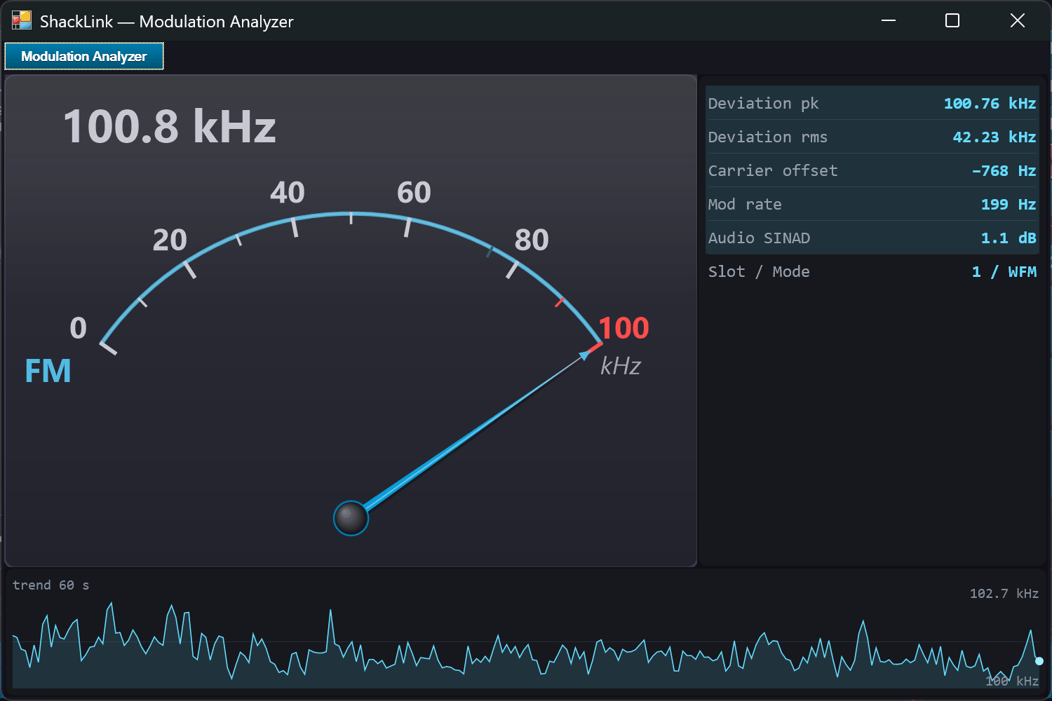
Modulation Analyzer: AM depth / FM deviation on an analog meter face, with the VSA table and trend
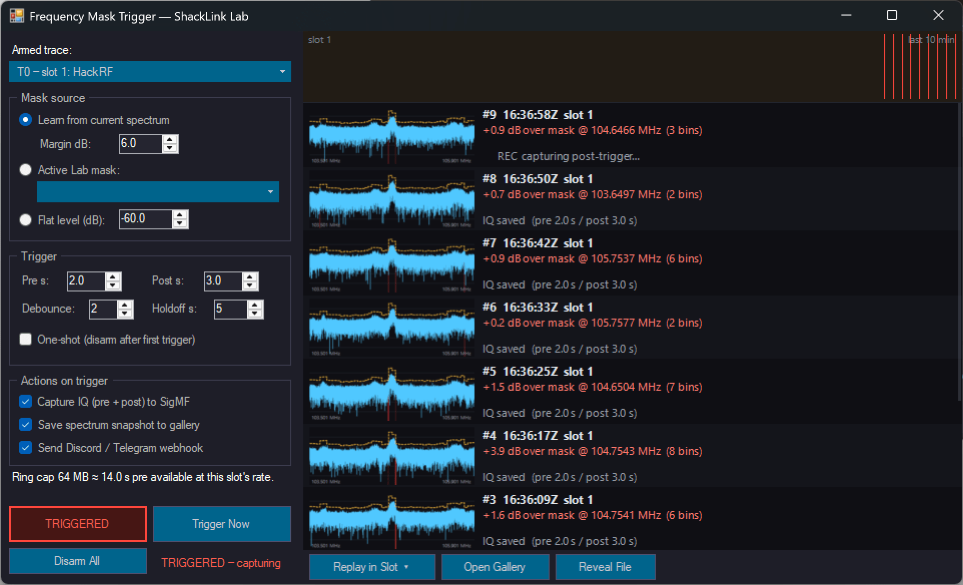
Mask Trigger: an armed limit mask with the event list and slot-lane timeline
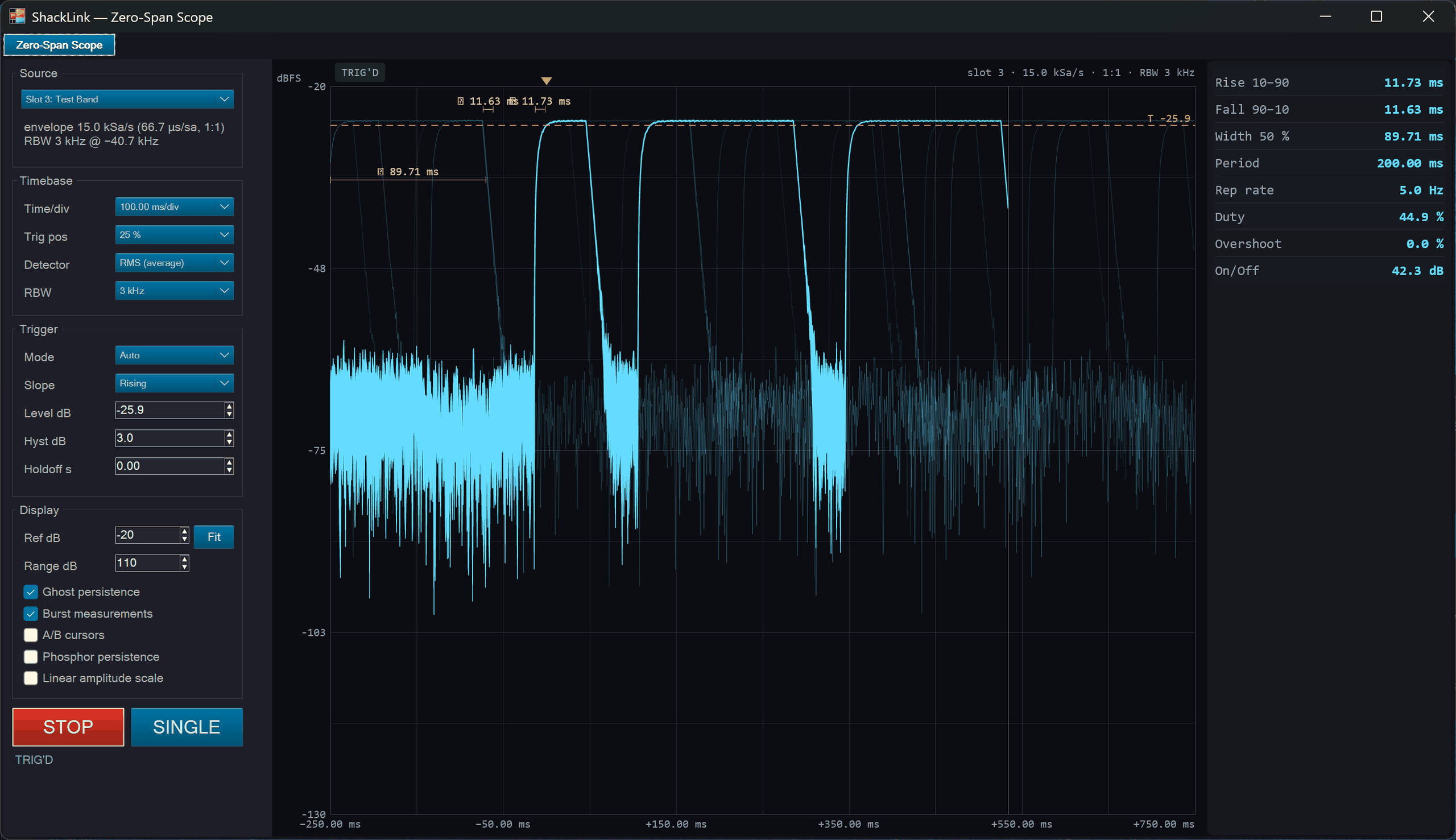
Zero-Span Scope: RF envelope vs time with scope triggering and burst measurements
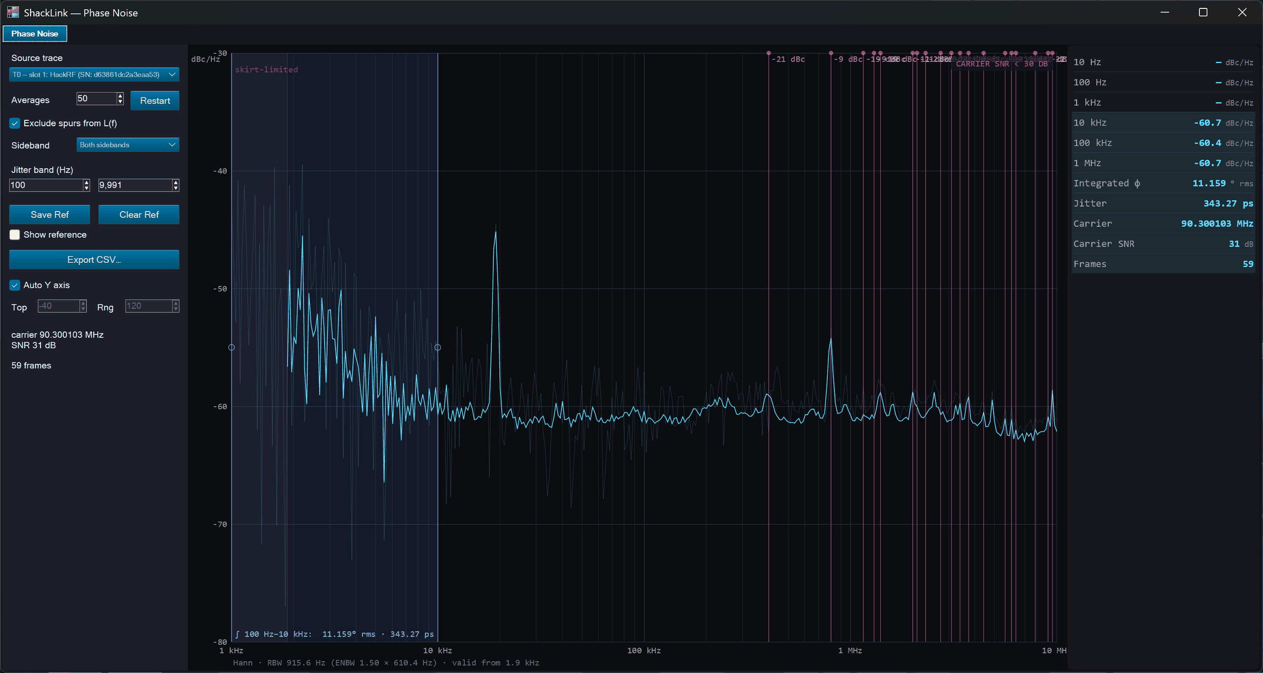
Phase Noise: L(f) in dBc/Hz vs log offset with the decade table and jitter

Noise Figure: the guided Y-factor wizard with the NF(f) / gain curves and ENR head profiles
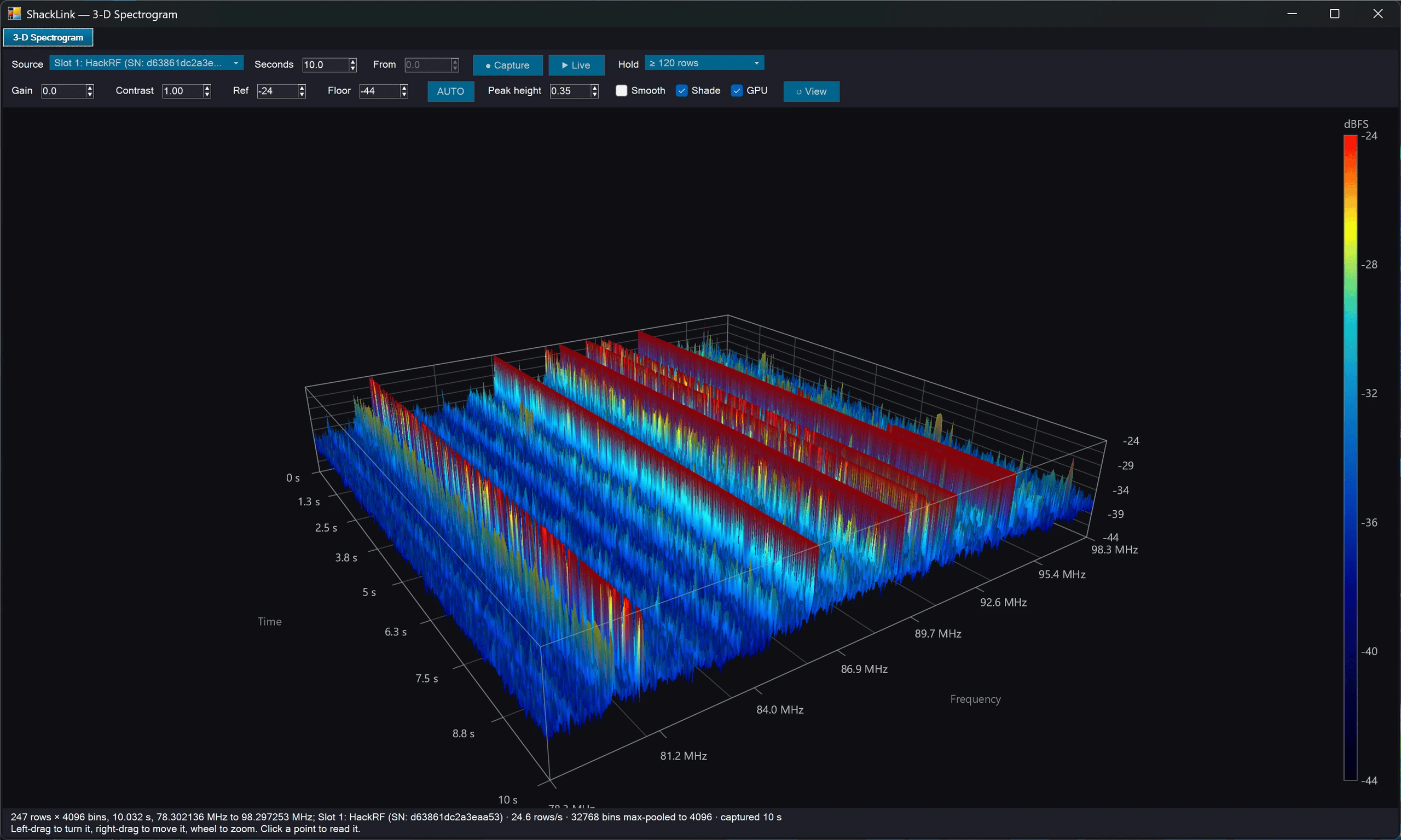
3-D Spectrogram: a block of sweeps you can turn round, with a picked sweep drawn over the surface
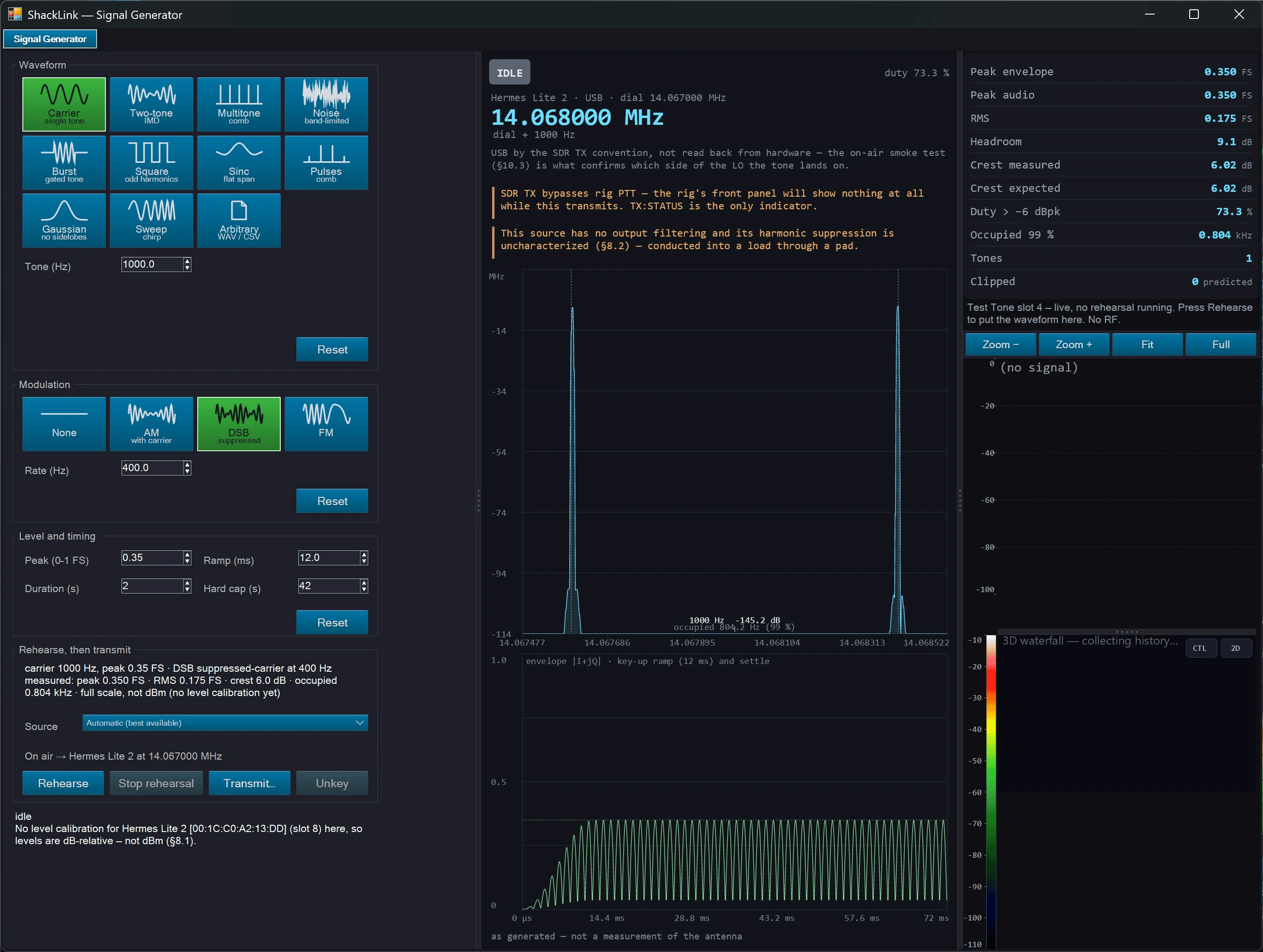
Signal Generator: waveforms and modulation picked from drawn pictures, rehearsed silently before anything is keyed
Advanced Tools
- Transfer function (S21): two-SDR stimulus/response measurement with calibration and limit-mask overlays. Export as Touchstone S1P/S2P
- Limit masks: regulatory and user-defined spectral masks for compliance visualization (spurious emission, harmonic suppression, bandpass)
- Scripts in C# or Python: a script reads traces, markers and measurements, sets the display, and records results. Pick the language from the editor’s drop-down; each comes with example scripts. New 2026-10: Python runs in its own worker process on the Python installed on your PC (numpy required, scipy welcome), which ShackLink finds for you or you choose. Scripts run with full trust, so the first script of each language in a session asks you to confirm. On the server a script can also read a slot’s raw I/Q — the “I/Q Peak” example finds the strongest signal in a block — without ever moving the receiver
- Cable loss compensation: predefined cable types and custom entry for length-based loss correction
- Export: CSV (all traces with frequency/amplitude columns), Touchstone S1P/S2P, PNG screenshot, and measurement log
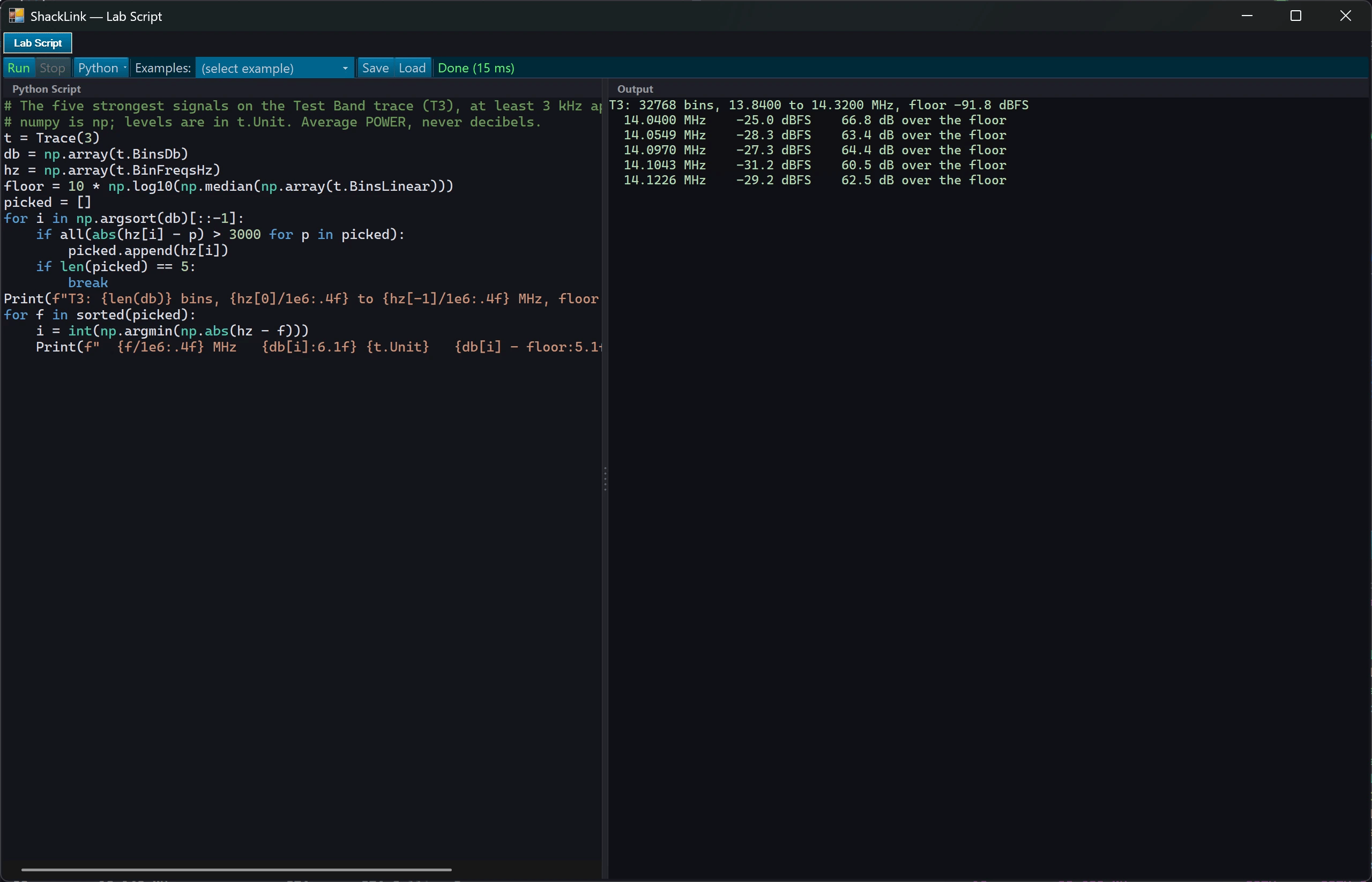
The Lab’s script editor running a Python example, with the language and interpreter picked from the editor’s drop-down
Tune From Spectrum
Enabled from the spectrum right-click menu (Tune From Spectrum), this turns the passive Lab display into an interactive listening surface that drives the SDR back-end:
- Select a trace: click a trace to highlight it; audio-follow switches to that trace’s SDR slot, so you now hear that device.
- Tune within the band: click again inside the selected trace’s band to move that slot’s demodulator (the listen point) to the clicked frequency.
- No re-center: tuning moves the listen point only; the SDR LO is not re-centered, so the trace stays put instead of jumping (previously the LO auto-centered on the click, which shifted the whole trace by megahertz on wide / FM-band spans). You tune within the currently captured span; to listen outside it, use Band Browse to move the window.
- Overlays: the selected trace can show a VFO frequency readout (Show Frequency) and a passband box (Show Passband).
- Peak markers: mark the top-N peaks on the selected trace. The Peak Markers submenu configures count (3–10), color, size (2–8 px), style (filled circle / outline / square / diamond), and optional frequency labels.
Band Browse
Active while Tune From Spectrum is on, Band Browse shifts a slot’s SDR LO so you can sweep across the band:
- Grab and drag a trace line horizontally, or click the plot then press Left/Right arrow keys, to shift that slot’s LO.
- Held listen frequency: if the slot is the audio-active (listening) one, the absolute listen frequency is held by compensating the demod offset. Audio mutes when the held frequency leaves the captured span and resumes when a later shift brings it back into span.
- Step size: with arrow keys, Shift = ×10 coarse step, Ctrl = fine step.
- Refused for rig-tracking slots and IF-panadapter mode, with a brief on-display “Locked” notice.
Shift Station to Edge
Also part of Tune From Spectrum, Shift Station to Edge parks a slot’s tuned signal at the left or right edge of its span (the server computes the LO from the listen frequency and demod mode). Pair a Right shift on a lower trace with a Left shift on a higher trace to butt two bands together for a wide, gap-free side-by-side view.
Popout Independence (Link Toggle)
The Lab popout window carries a Link toggle. Linked, it mirrors the tab: mode, settings, and data stay in lock-step. Unlinked, the popout becomes fully independent, with its own zoom, amplitude scale, palette, 3D camera, and pane layout (all persisted separately), so you can keep a wide overview on the tab and a zoomed detail view in the popout at the same time.
No-Data Legend Status
A checked (visible) trace whose SDR source is not delivering data still appears in the spectrum legend, its name shown dimmed with a short status word (Not started, No data, or Unavailable) in place of a frequency range, so you can see the trace is selected but waiting on its device.
Desktop Client Support
The full Lab tab is available on the desktop client with identical functionality. All UI code is shared via <Compile Include> links. The client’s SdrStreamPlayer feeds the same TraceEngine with SDL1 frames from the server’s spectrum stream (TCP 8085). Persistence, popout, scripting, transfer function, and export all work identically on both server and client. Two things need the server’s own receivers and stay there: a script’s raw I/Q reads, and the 3-D spectrogram of a recording.
Architecture
The Lab tab is a passive overlay on existing SDR spectrum data by default. When Tune From Spectrum is enabled it can select the audio slot (which device you hear), tune a slot’s demodulator listen point, and (for Band Browse) shift a slot’s LO; it still never alters the SDR capture pipeline or FFT. The desktop client uses dedicated commands for these actions (SDR:<n>:DEMODTUNE:<absHz> / SDR:<n>:LOSHIFT:<Hz> over TCP, sdrDemodTune / sdrLoShift over WebSocket); the server’s own SDR-tab panadapter click still re-centers as before, so only the Lab tune is no-re-center. The engine library (ShackLinkLab, netstandard2.0) provides TraceEngine, MarkerEngine, MeasurementEngine, PersistenceEngine, TransferFunctionEngine, LimitMaskEngine, CcdfEngine, and ScriptHost. UI rendering uses SkiaSharp with double-buffered offscreen compositing and GDI+ blit. Total CPU budget at full load (8 traces, 8 markers, persistence, spectrogram): ~15–20 ms per 33 ms frame.
📊 Audio Visualization
Real-time audio visualization with multiple display modes and customizable themes.

Waterfall (2D) on the Audio tab

Waterfall (3D terrain)

Oscilloscope: time-domain waveform

Visualization popout: 2D waterfall in its own window

Visualization popout: 3D terrain waterfall on a second monitor
Opening the Visualization Window
The Audio tab shows the visualization, and the Visualization tile on the Tools tab opens it in its own window, which stays open while you work with other controls. Its settings live on the display’s right-click menu.
Visualization Modes
🌊 Waterfall
Scrolling spectrogram display showing frequency over time. New data appears at top and scrolls down. Includes a smooth spectrum curve overlay. Great for identifying signals and monitoring band activity.
📈 Spectrum (Bars)
Classic bar-style spectrum analyzer with peak hold indicators. Shows real-time frequency amplitude across the audio passband. Peaks slowly decay to show recent maximum levels.
💡 Spectrum (LEDs)
Retro LED-style segmented display reminiscent of vintage audio equipment. 32 segments per bar with configurable peak indicators. Adjustable peak height from 1-10 pixels.
💨 Oscilloscope
Time-domain waveform display showing the raw audio signal. Useful for monitoring signal levels and identifying modulation patterns.
Tuning from the Waterfall
The audio waterfall is tunable everywhere it appears: the Audio tab, the photo panel, and the Visualization popout.
Hover the audio waterfall and a dim ghost cursor follows the pointer, reading out the frequency under it, and, for modes you can retune, a preview of the decoder’s passband centred on the cursor, so you can see how it would sit on the signal before you commit. Click to place the decoder there. The marker then shows where the decoder actually landed, so if the value was out of range you see the clamp rather than a marker that quietly disagrees.
Only PSK31, Olivia and NAVTEX have a centre frequency to move; in other modes the click just parks the marker. Note that this sets the decoder’s centre frequency inside the audio passband: it is not the SDR waterfall’s click-to-tune, and the radio does not move.
Decoder Passband
A translucent decoder passband rectangle shows the span the active decoder is listening across: Olivia’s exact bandwidth (16/500 = 500 Hz), PSK31’s symbol rate, RTTY’s live auto-detected mark/space rails, and the fixed tone rails for NAVTEX, APRS, SSTV, WEFAX and CW. It is the nominal occupied span: an alignment aid, not a measured bandwidth. Right-click → Decoder Passband toggles it.
FT8, WSPR and JS8 show no passband: those are decoded by WSJT-X / JS8Call, not by ShackLink, so there is nothing honest to draw.
Palettes
The waterfall and the spectrum use the same named palettes as the SDR display — Classic (blue), Classic (green), CoolWarm, Viridis, Plasma, Inferno, Grayscale, Neon (cyan), Signal (teal), Semaphore, Rainbow and the rest — picked from a grid of small rendered waterfalls on the right-click menu, so a palette of a given name looks the same on every surface.
Display Settings
- Sensitivity – Adjust input gain for optimal display levels
- Contrast – Control the dynamic range of the visualization
- Freq Range – Set the maximum displayed frequency
- Peak Color – Choose peak indicator color (theme-based options)
- Peak Height – Set peak indicator height (1-10 pixels)
- Reverse – Flip waterfall scroll direction (new data at bottom)
💡 Settings Persistence
All visualization settings are automatically saved and restored between sessions. The window also remembers its position and size.
🔢 Digital Decoders
The server decodes twelve digital modes: CW (Morse), RTTY, PSK31, FT8, FT4, SSTV, WEFAX, NAVTEX, APRS, WSPR (relayed from WSJT-X), JS8 (bridged from JS8Call), and Olivia/Contestia. Select the decoder mode from the dropdown to switch between them: the choice is broadcast to every connected client.
Ten of the twelve are native: ShackLink does the DSP itself, so nothing else needs to be installed. WSPR and JS8 are bridged (from WSJT-X and JS8Call respectively) and only produce anything while that program is running. FT8 and FT4 can be either: the Engine picker on the FT8 panel selects the native decoder or the WSJT-X bridge, and the two are indistinguishable downstream. The bridge remains the shipped default while the native engine accumulates on-air hours.

CW (Morse): signal scope, element display, and decoded text

SSTV: image on the left, live audio-band waterfall on the right
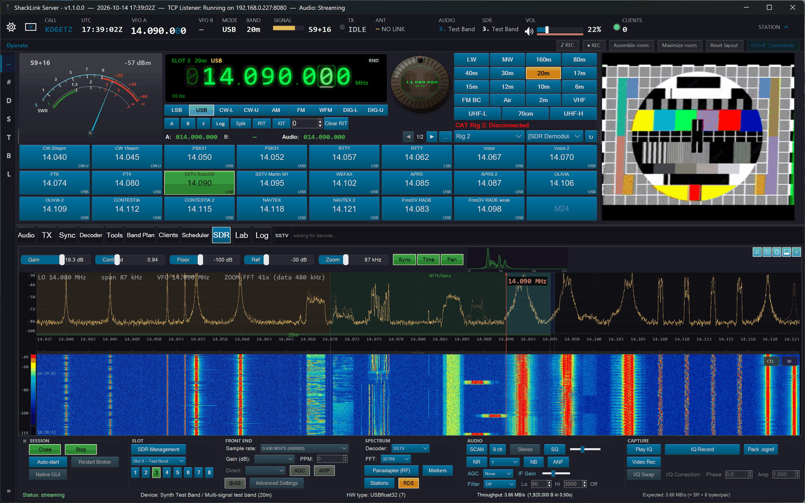
A decoded image mirrored in the dashboard panel
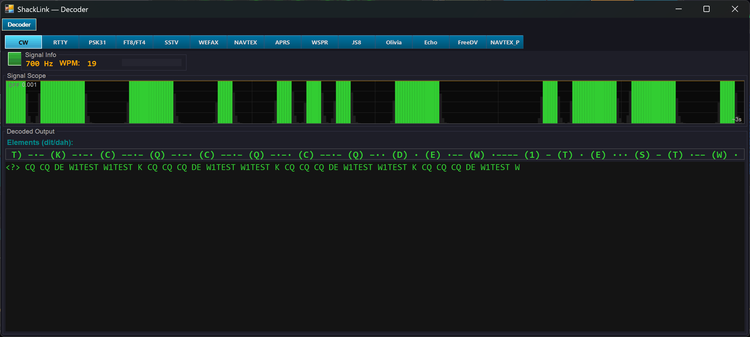
Decoder popout: CW in its own window
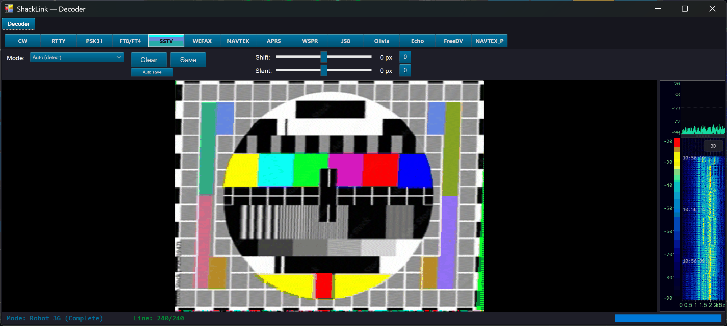
Expand to Window: the detachable full-size decoder with image + waterfall
Morse (CW) Decoder
- Select CW (Morse) from the decoder mode dropdown
- Enable the decoder checkbox
- Choose decoder algorithm: Speed Priority or Accuracy Priority
- Decoded text appears in the display and streams to clients
RTTY Decoder
- Select RTTY from the decoder mode dropdown
- Enable the decoder checkbox
- The decoder auto-detects baud rate (45.45 or 50 baud) and shift (170/425/850 Hz)
- Monitor signal quality and lock status indicators
- Decoded text appears in the display and streams to clients
PSK31 Decoder
- Select PSK31 from the decoder mode dropdown
- Pick a modulation mode (9 variants):
- BPSK-31 / BPSK-63 / BPSK-125: binary PSK at 31.25, 62.5, or 125 baud
- QPSK-L-31/63/125: quadrature PSK with Viterbi FEC, lower sideband
- QPSK-U-31/63/125: quadrature PSK with Viterbi FEC, upper sideband
- Set the center frequency (200–3000 Hz) to match the signal in the audio passband
- Enable AFC to automatically track frequency drift
- Enable FEC for Viterbi forward error correction on QPSK modes
- Adjust squelch to filter noise when no signal is present
- Decoded text appears in the display and streams to clients
SSTV Decoder
Receives Slow Scan Television images on voice modes (typically USB). The SSTV panel embeds a split view directly in the Decoder tab: decoded image on the left, live waterfall of the SSTV audio band (1200–2300 Hz) on the right, with a draggable splitter between the two so you can rebalance their sizes. A thin status strip at the bottom shows detected mode, current line, and progress.
- Select SSTV from the decoder mode dropdown
- Tune to a known SSTV frequency (e.g., 14.230 MHz USB on 20 m)
- The decoder auto-detects the mode from the VIS header and renders the image line-by-line alongside the waterfall
- For weak signals where VIS detection fails, pick a Forced Mode (e.g.,
Robot36). ChooseAUTOto return to detection. - Right-click the image for Save / Clear / “Expand to Window” (the last opens a detachable full-size decoder window with the same layout).
- Clients that connect mid-decode receive a catch-up stream so their display syncs with the server.
Supported modes (20 total): Robot 36 / 72 / 8BW / 24BW, Martin M1 / M2, Scottie S1 / S2 / DX, PD 90 / 120 / 160 / 180 / 240 / 290, Wraase SC2-120 / SC2-180, Pasokon P3 / P5 / P7. (PD50 also decodes when auto-detected from the VIS header, but is not offered in the forced-mode picker. Transmit covers 19: the Robot BW modes are receive-only.)
FT8 / FT4 — Decoding, the QSO Console and Logging
FT8 and FT4 are decoded either by ShackLink’s own native decoder or by a co-located WSJT-X over UDP port 2237. Pick one with the Engine selector on the Decoder tab’s FT8 panel; the two look identical downstream. The WSJT-X bridge is still the default. If you choose it, run WSJT-X and enable File → Settings → Reporting → UDP Server on port 2237; the console says plainly when no WSJT-X is connected, so pick Native if you do not run it.
- Select FT8 or FT4 from the decoder buttons
- Decodes (time, SNR, DT, Δf, message) appear in the list and are broadcast to clients with SNR-based color coding; the cycle-locked wide graph draws a box around every decode
- Double-click a decode to answer it, arm Enable TX, and the QSO console sequences the contact; Tx1–Tx6, Auto-seq and Hold TX freq work as in WSJT-X
- When the contact completes, the log entry carries the contact’s own start and end times, frequency, mode and the report actually sent. With auto-log off you are asked first; a contact a desktop client drove is offered to that client
- The console’s Options menu sets auto-log, the repeat limit, the TX watchdog, a final 73, RRR instead of RR73, and a CQ modifier
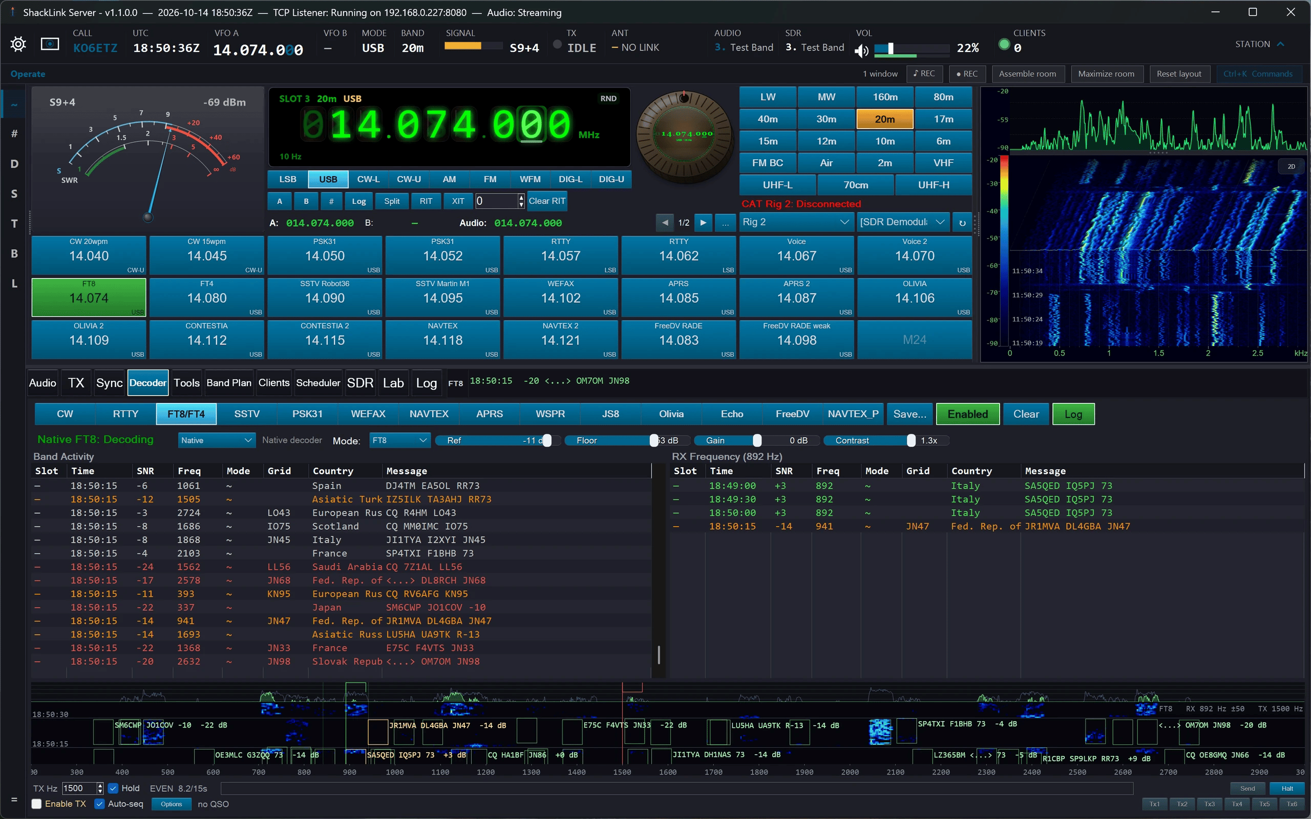
The Decoder tab on FT8: the decode lists, the cycle-locked wide graph, and the QSO console with its compose strip
WEFAX Decoder (Weather Facsimile)
Receives grayscale weather charts on HF marine bands. The WEFAX panel uses the same split layout as SSTV: image on the left, live waterfall of the WEFAX audio band on the right, draggable splitter, status strip showing line / progress at the bottom. Slant / shift sliders correct any residual alignment drift.
- Select WEFAX from the decoder dropdown
- Tune to a known WEFAX broadcast (e.g. NOAA: 4346 / 8503.9 / 12789.9 kHz USB; DWD Hamburg: 3855 / 7880 / 13882.5 kHz USB)
- The decoder runs a phasing-lock detector first: looks for the white phasing pulse pattern that precedes the image and aligns the line phase from it. Mid-stream joins fall back to the legacy fold/cluster sync path automatically.
- Use the slant / shift sliders on noisy captures with broadcaster clock drift
- Save / Clear / Expand to Window via the toolbar or right-click on the image
NAVTEX Decoder (Maritime Safety)
Receives NAVTEX maritime safety broadcasts on 490 / 518 / 4209.5 kHz. The decoder implements the SITOR-B forward error correction protocol (CCIR 476, 100 baud, 170 Hz shift).
- Select NAVTEX from the decoder dropdown
- Tune to a NAVTEX broadcast frequency (e.g. 518 kHz for international English, 490 kHz for national language)
- Decoded characters appear in the text display and stream to all connected clients
APRS Decoder (Packet Radio)
Decodes AX.25 1200 baud Bell 202 AFSK packets. Displays callsign, position, and message data from APRS beacons.
- Select APRS from the decoder dropdown
- Tune to 144.390 MHz (North America) or 144.800 MHz (Europe/most regions) on FM
- Decoded packets appear as one-line summaries showing source callsign, position coordinates, and beacon text
WSPR (via WSJT-X)
Weak-signal propagation spots relayed from a co-located WSJT-X running in WSPR mode, over the same UDP port 2237 that carries FT8. Each spot is enriched on the server with the DXCC country plus the distance and bearing from your grid square, so no client has to do lookups of its own.
- Run WSJT-X in WSPR mode, with File → Settings → Reporting → UDP Server enabled on port
2237 - On the server, select WSPR from the decoder dropdown
- Spots (time, SNR, drift, frequency, callsign, grid, power, distance, bearing, country) appear in the list and stream to every client
- The last 100 spots replay when a client subscribes, so a client that joins late still sees the recent picture
Spots also draw greyline paths on the map (transmitter at the spot’s grid, receiver at your QTH) and can fire a webhook for watch-list callsigns or a new DXCC this run. The webhook is off by default.
⚠️ One WSJT-X instance decodes either FT8 or WSPR
A single WSJT-X does one or the other, never both at once. To run WSPR alongside FT8, start a second instance with --rig-name; ShackLink tracks the two separately. Like FT8, WSPR is a bridged mode, so it cannot be assigned to an individual SDR slot.
JS8 (via JS8Call)
Keyboard-to-keyboard JS8 traffic bridged from a running JS8Call instance over its TCP API (default 127.0.0.1:2442). ShackLink mirrors JS8Call’s state rather than decoding the audio itself.
- Run JS8Call and enable Settings → Reporting → TCP Server API. Without it there is nothing for ShackLink to connect to.
- On the server, select JS8 from the decoder dropdown. The host and port are settings, if you moved JS8Call off its defaults.
- Directed messages arrive DXCC-enriched, with the last 50 replayed when a client subscribes. Traffic addressed to your callsign is highlighted and can fire a webhook.
- Band activity shows raw frames as they land (often fragments, mid-word) rendered as-is rather than parsed
- Spots, the station’s identity, and the current speed (normal / fast / turbo / slow) mirror alongside
- Transmit: type a message and ShackLink queues it for JS8Call’s next cycle
⚠️ JS8Call owns its own keying
JS8 transmit is not one of the TX-mode picks: it queues through the bridge. While JS8Call keys the rig, ShackLink’s own transmit paths refuse with TX:LOCKED:JS8CALL. That is an advisory lock inside ShackLink, not a hardware interlock. JS8 is a bridged mode, so it cannot be assigned to an individual SDR slot.
Olivia / Contestia Decoder
A native MFSK decoder: no external program needed. Tone sets run from 4 to 64 tones across 125–2000 Hz of bandwidth, with 8/250, 16/500 and 32/1000 the common on-air presets. Contestia is a family setting inside this mode, not a separate mode. Transmit is supported as well.
- Select Olivia/Contestia from the decoder dropdown
- Pick the family (Olivia or Contestia) and the format (tones / bandwidth) to match the signal
- Set the center frequency onto the signal, or click it straight off the audio waterfall (see Tuning from the Waterfall above)
- Leave Squelch at its default of 3 unless you have a specific reason not to (see below)
- Decoded text appears in the display and streams to clients
⚠️ Squelch is a sync-confidence threshold, not an audio level
This is the setting that catches people out. Olivia’s Squelch is a sync-confidence threshold, not an audio level. The default (3) is junk-free: it will not print garbage when the signal drops. Setting it to 1 turns it off, which buys roughly 2 dB more sensitivity but prints junk on sync loss. 10 only decodes solid signals.
Measured sensitivity, strict full-text decode, AWGN, 2.5 kHz reference:
| Format | Default squelch 3 | Squelch 1 (off) |
|---|---|---|
| 8/250 | −14 dB | −16 dB |
| 16/500 | −12 dB | −14 dB |
| 32/1000 | −12 dB | −14 dB |
| Contestia | −12 dB | −12 dB |
Image TX (SSTV + WEFAX)
The TX tab supports sending images directly from the server (or any client). When you switch the TX-mode picker to SSTV or WEFAX, the chat panel swaps in an ImageTxPanel:
- Pick mode (SSTV: 18 sub-modes; WEFAX: IOC 576/288, LPM 60/120)
- Choose Image: the panel resamples and shows a preview
- Click Send: the encoder runs, PTT keys via OmniRig, the live build-up appears in the preview as the encoder transmits
- Test (no RF) mode: encoder runs but PTT stays low, for offline rehearsal. A WAV is saved next to the source image automatically.
- Non-transmitting clients see
TX:STATUSandTX:PROGRESSso they can follow the line counter
From a remote client (web / mobile), the image is uploaded chunked over the WebSocket binary channel 0x04, SHA-256 verified, then staged server-side (per-client cap of 4, 10-min idle GC, 5 MB max). After staging, TX:KEY:SSTV:<imageId>:<mode> or TX:KEY:WEFAX:<imageId>:<ioc>:<lpm> kicks off the encoder.
Slot Decoders
Each SDR slot can run its own decoder on its own audio — CW, RTTY, PSK31, NAVTEX, APRS, Olivia, FT8 or FT4 — set in SDR Management or from any client. The Slot Decoders window shows all of them at once: a lane per text-mode slot with its live transcript, and a table of FT8/FT4 records. A lane is dimmed rather than removed when its decoder stops, so the text stays attributable.
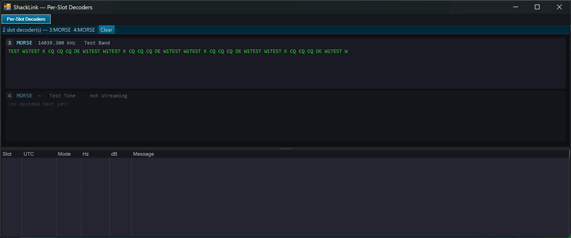
The Slot Decoders console: every slot’s own decoder in one window
Plug-in Decoders and the Plugin Manager
Decoders can be added as plug-ins with no new ShackLink release. Plugins… on the Tools tab opens the Plugin Manager: it lists every installed plug-in and where it can run, and it installs, disables and removes them. Installed plug-ins live in your own %LocalAppData%\ShackLink\Decoders folder (Open Folder takes you there), so an installed server needs no administrator rights. Because Windows cannot unload a running DLL, an install or a removal takes effect at the next start, while Disable takes effect at once. The install kit ships the FreeDV decoder as an optional part, and a channel-occupancy logger with the server. Plug-ins run with full trust: install only what you trust.
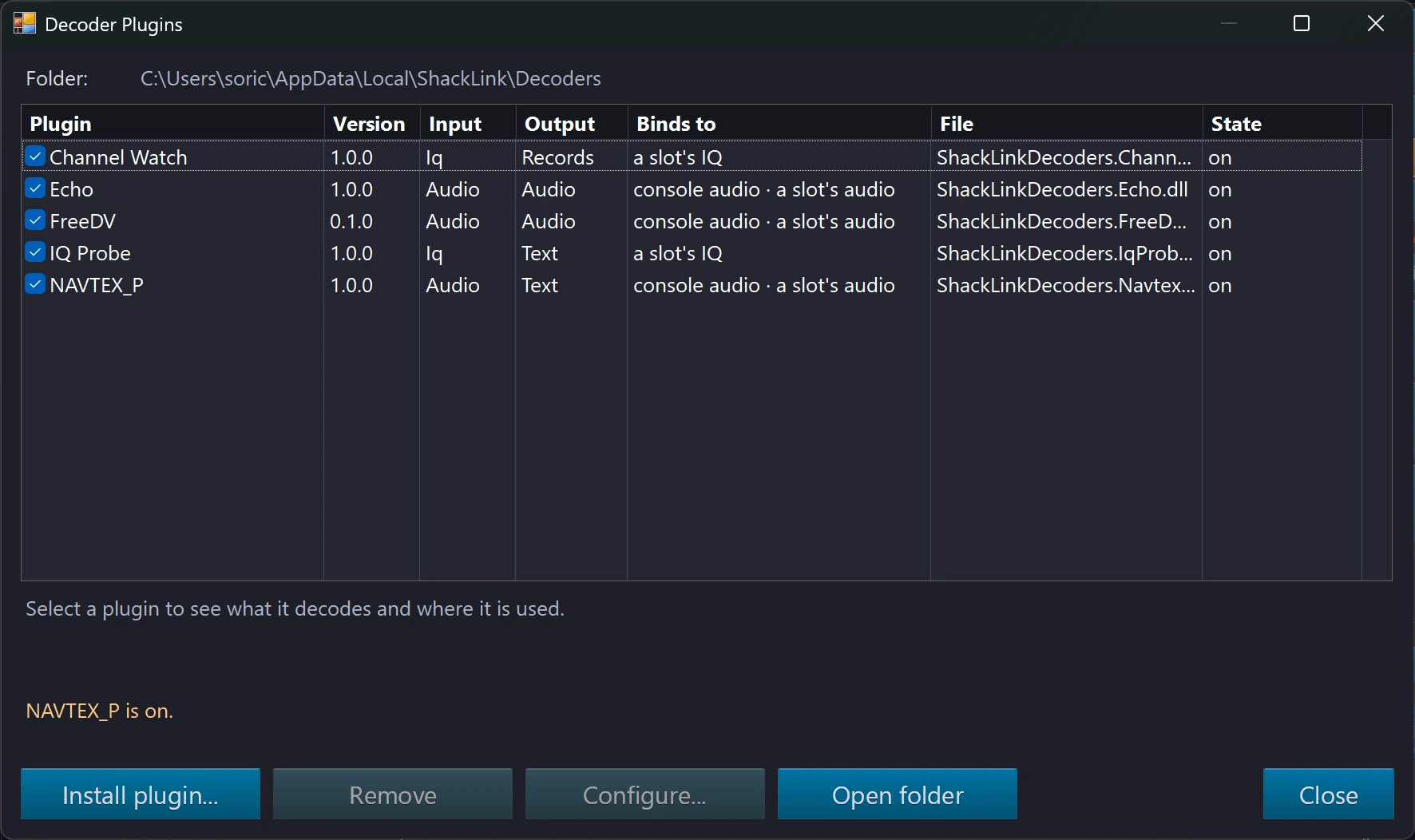
The Plugin Manager: every installed plug-in, where it binds, and Install, Disable and Remove
💡 Why Server-Side Decoding?
Server-side decoding is more accurate than client-side because it processes the original audio without network jitter artifacts. CW works reliably at speeds up to 40+ WPM, RTTY auto-detects standard amateur radio parameters, PSK31 tracks drifting signals with AFC, and SSTV catches every image in full resolution.
Saving Decoded Text
Click the Save… button to save decoded text to a file. The default filename includes the decoder mode (cw/rtty/psk31) and timestamp. SSTV images can be saved via the Save button above the split, by right-clicking the image, or from the detached “Expand to Window” view.
📧 Winlink Radio E-mail
A native Winlink client: the mailbox on the server, sessions over the internet or the radio, operated at the station.
Winlink is the amateur-radio e-mail system. ShackLink composes, sends, receives and keeps Winlink mail itself — folders, attachments, a size estimate against the gateway limit, replies and forwards — and reaches the network two ways:
- Over the internet to the Winlink CMS, with the secure login every path requires.
- Over the radio through the modem program you already run — VARA HF, VARA FM, ARDOP, or a packet engine’s AGWPE port (Direwolf, UZ7HO SoundModem). ShackLink sets the dial and mode, holds the transmit lock for the whole session, keys the rig when the modem asks, and releases everything at the end, with every interlock an ordinary key-up has.
- A gateway table with distance and bearing from your locator, hand-entered or fetched from Winlink with a Web Services key.
- Session kinds: Winlink mail, peer-to-peer (directly to another station) and Radio-Only. A message is only ever offered to a session of its own kind.
- Station services that travel as ordinary messages: catalog requests, position reports from your grid, account options and the whitelist.
- Winlink’s standard forms (ICS-213 and the rest), imported from a Winlink Express template pack into ShackLink’s own store and filled in an embedded browser; a received form is drawn with the sender’s values.
- An account is created only on purpose (new 2026-10): a first Connect with no password no longer turns into a new Winlink account. On a reinstalled station that would be the wrong answer, so creating one is its own button — Account… → Create account… — and asks once, naming the callsign, the transport and the gateway.
- Operated at the station (changed 2026-10): the desktop client, web client and mobile app no longer carry a mailbox. Winlink is used from the server’s own screen, and the account password never leaves it.
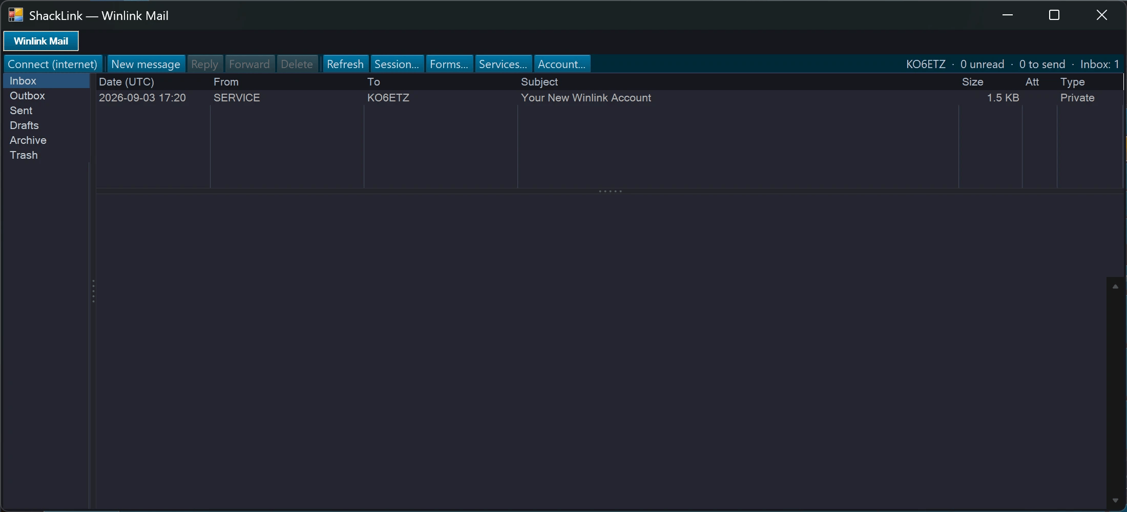
The Winlink mailbox window on the server: folders, the message list and a preview
Internet sessions have run against Winlink’s servers; no radio session has reached a gateway on the air yet.
Winlink’s production servers admit only client programs Winlink has registered, so ShackLink identifies itself honestly and uses the server Winlink names for the rest (cms-z.winlink.org). The account was created and mail received there. The modem programs are your own installations; none is bundled.
🎙 FreeDV Digital Voice
RADE and the classic modes, receive and transmit, as a drop-in decoder.
The FreeDV plug-in runs RADE — the machine-learning mode most FreeDV stations now use — and the classic 1600, 700C, 700D and 700E modes. On receive, the decoded speech replaces the console audio for every listener, the audio waterfall marks where the modem locked, and the callsign in a RADE station’s end-of-over frame is written on every audio waterfall. On transmit, the operator’s microphone goes through the modem on the ordinary voice PTT, with a transmit waterfall on the TX tab and the station’s callsign in the end-of-over frame. The plug-in cannot be swapped while it is transmitting, so the raw microphone can never reach the air.
The transmit chain is bit-identical to the reference FreeDV tools and has keyed a real radio into a dummy load; on-air contacts are still to come. The plug-in and its native libraries are an optional part of the install kit (FreeDV digital voice decoder).
📍 Band Plan (Frequency Table)
Built-in searchable reference of amateur allocations and common operating frequencies.

Band Plan embedded in the tab area

Popped out to its own window alongside the main UI
Open the Band Plan tab, or the Band Plan tile on the Tools tab for a separate window. It stays open alongside the main UI so you can hop around the band quickly.
Using the Band Plan
- Filter by band category (HF, VHF, UHF) and by mode with the quick-filter buttons
- Search by frequency, band name, or description
- Select a row and click Tune (or double-click) to set the radio to that frequency and mode
- The current row auto-highlights as the radio frequency changes
- Calling frequencies are visually distinguished
🎨 Themes, finishes & styles
Twenty-three colour themes (three of them light), fifteen button finishes, and independent dial and knob style sets.
Nothing here is a skin over a fixed layout — the palette drives the whole window (readouts, meters, panels, buttons, and every dropdown menu), the button finish is a separate axis from colour, and the VFO dial and the tuning knob each carry their own style set. They combine freely, so the pictures below are one axis at a time.
Light themes (new 2026-09-14): ShackLink Light, Paper and Blueprint. Light or dark is decided by the palette, not by a separate mode switch, and a light theme was designed and contrast-checked as a whole rather than produced by swapping a dark one’s background. The instruments follow it — scopes, navigators, Lab panes, meters, decoder scopes and instrument windows go light, the VFO readout becomes a paper screen with dark ink, and each waterfall palette is drawn as its designed light twin — with one switch to keep the dark instrument look and another to keep only the waterfalls dark. Four light dial styles (Paper, Blueprint, E-Ink, Enamel) and four light knob styles (Ivory Bakelite, Frosted Acrylic, Flat Light, Anodised Silver) joined the sets, for twenty and twenty-three in all. The web client stays dark on purpose.
A picture behind the app (new 2026-09-03): Station Settings → Background Image… shows one picture across the window wherever the app paints its own background, at the strength you choose; each SDR spectrum carries its own picture setting, with the waterfall fading as the picture strengthens.
🛠 Tools & Dashboards
Additional server-side tools, launched from the Tools tab’s grid of tiles.
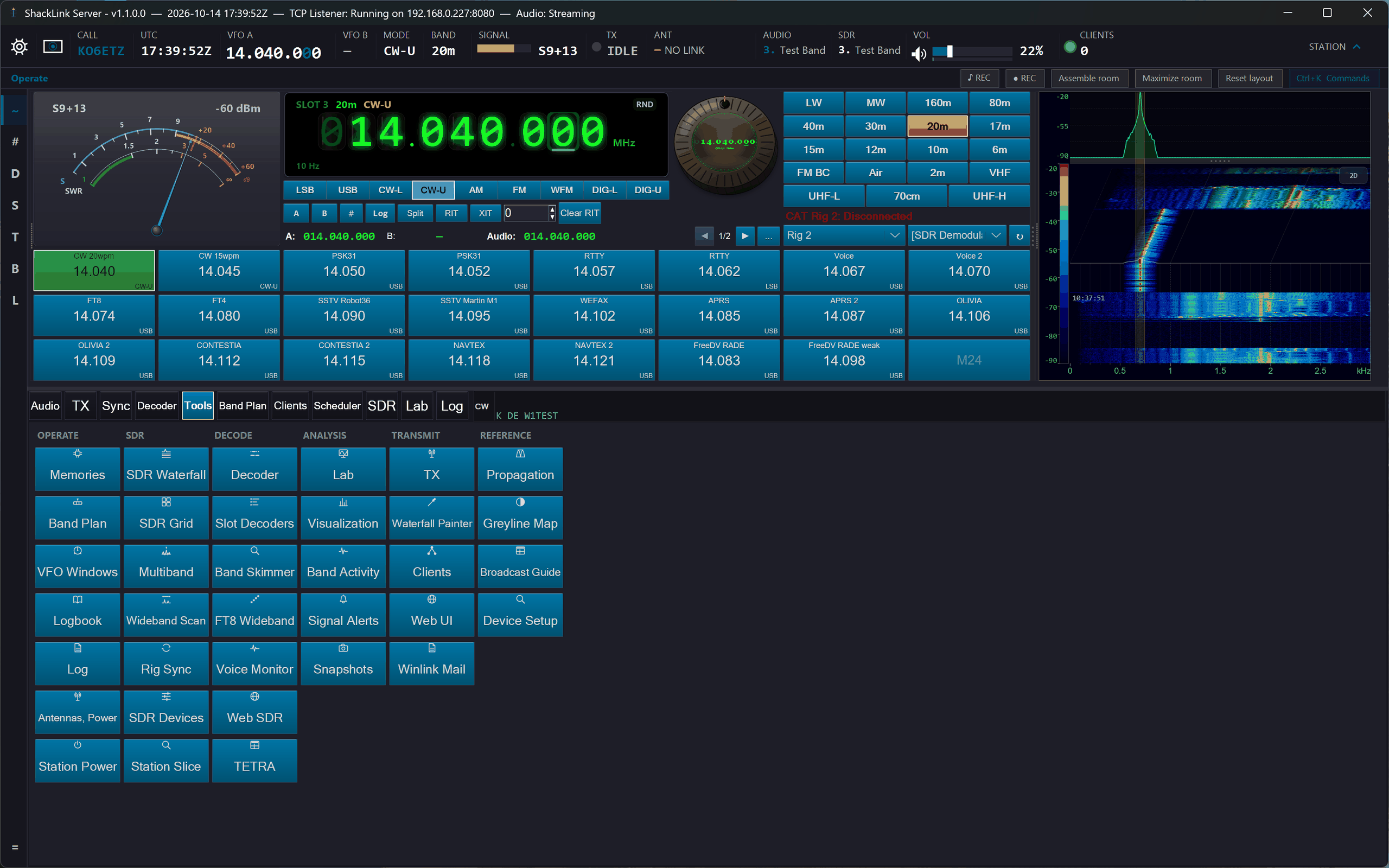
The Tools tab: launcher tiles in six captioned columns (Operate, SDR, Decode, Analysis, Transmit, Reference). Settings moved behind the flight strip’s gear, into the Station Settings window.
Start Menu
The flight strip’s gear opens a Start menu: a tile for every window and tool, grouped by activity, with search, pinned favourites, and a Settings category holding a tile for each Station Settings block. It is built from the same command list as Ctrl+K, so the two always agree. Touch mode’s MORE page shows these same tiles on finger-sized keys.
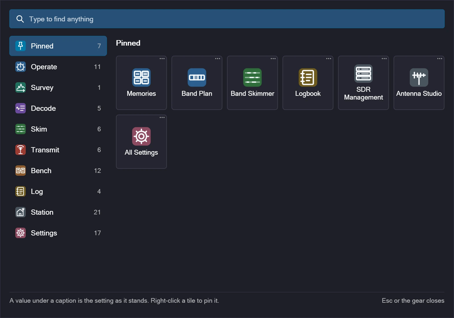
The Start menu behind the gear: every tool as a tile, grouped by activity, with search and pins
Device Setup
New 2026-10. Tools → Device Setup answers “is my radio ready, and what do I do next?” It has one card per supported device — RTL-SDR, HackRF, SDRplay, SoapySDR radios, USRP B2xx, PlutoSDR, Hermes Lite 2, web receivers, OmniRig, Icom, ExtIO and sound-card I/Q. A check looks at this PC (driver files, the USB drivers Windows has given each device, the SDRplay service, the slots already running) without opening any radio, and each card then says in plain English where that device stands, with the exact steps for its state.
- A button that does the step, where that is safe: fetch the RTL-SDR Blog driver files into your own
%LocalAppData%\ShackLink\rtl_tcpfolder (no administrator rights needed), start Zadig already set to show every device and pick WinUSB, or install Analog Devices’ PlutoSDR USB drivers. - Nothing is fetched without asking. A consent dialog names the file, where it comes from, its publisher, its licence and where it will go, and every download is checked against a pinned size and fingerprint before it is used. These files come from their publishers, not from ShackLink.
- Where a click-through licence or a large installer is involved (the SDRplay API, UHD, radioconda, OmniRig, Icom’s USB driver), the card opens the right download page and lists the steps instead.
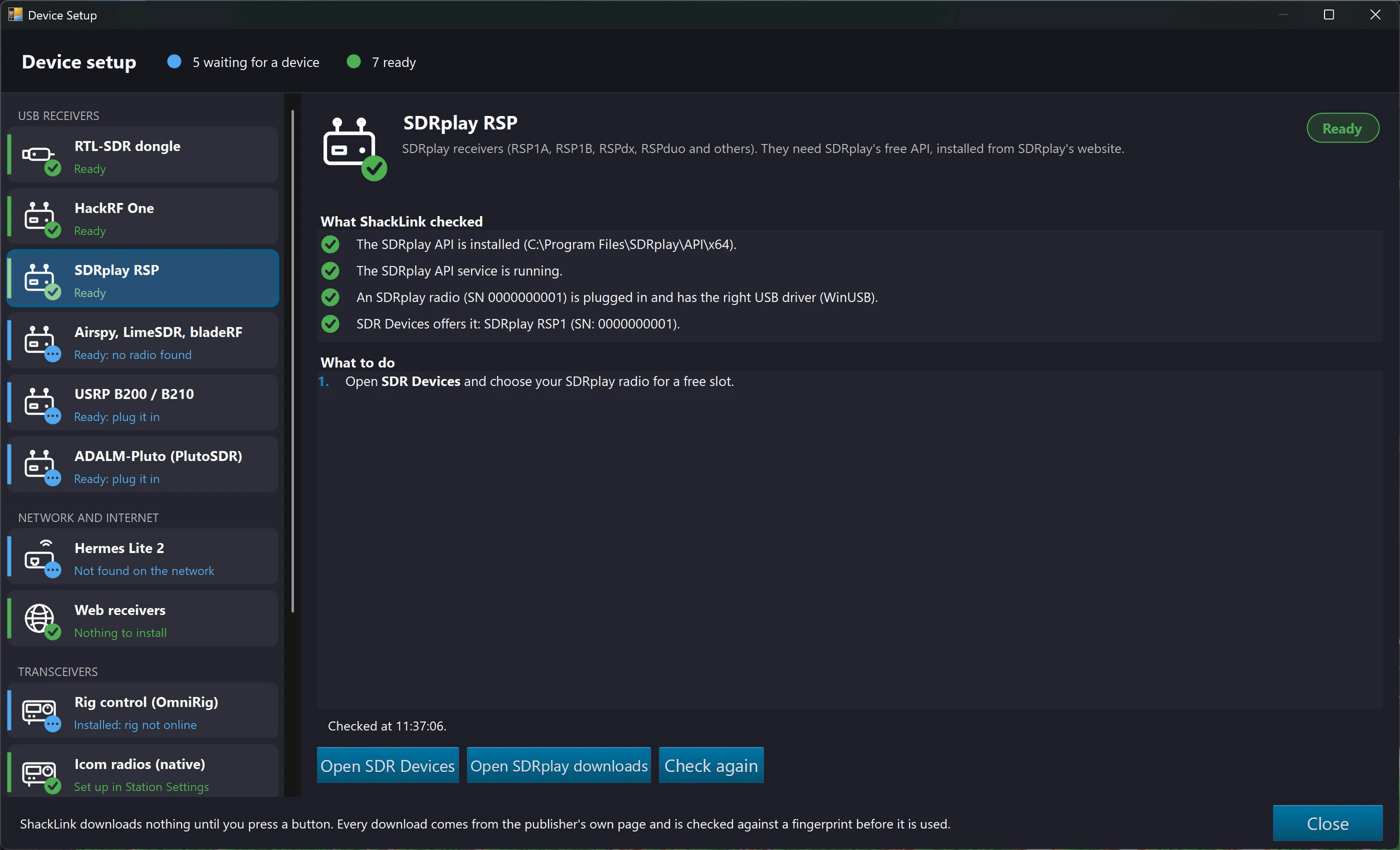
Device Setup: a card per device, what this PC has, and the next step in plain English
Custom Colors
Click Colors in the Station Settings window (the flight strip’s gear → Settings) to open a color customization dialog — 60 colours in eleven groups. Personalize the frequency display, meters, background, accent colors, and other UI elements. Changes are saved and restored between sessions. Beyond individual accents, several complete color themes re-tint the whole window in one click from the Colors dialog or the title-bar Theme menu.

Color Settings, previewed live (an earlier capture: the dialog now carries 60 colours in eleven groups)
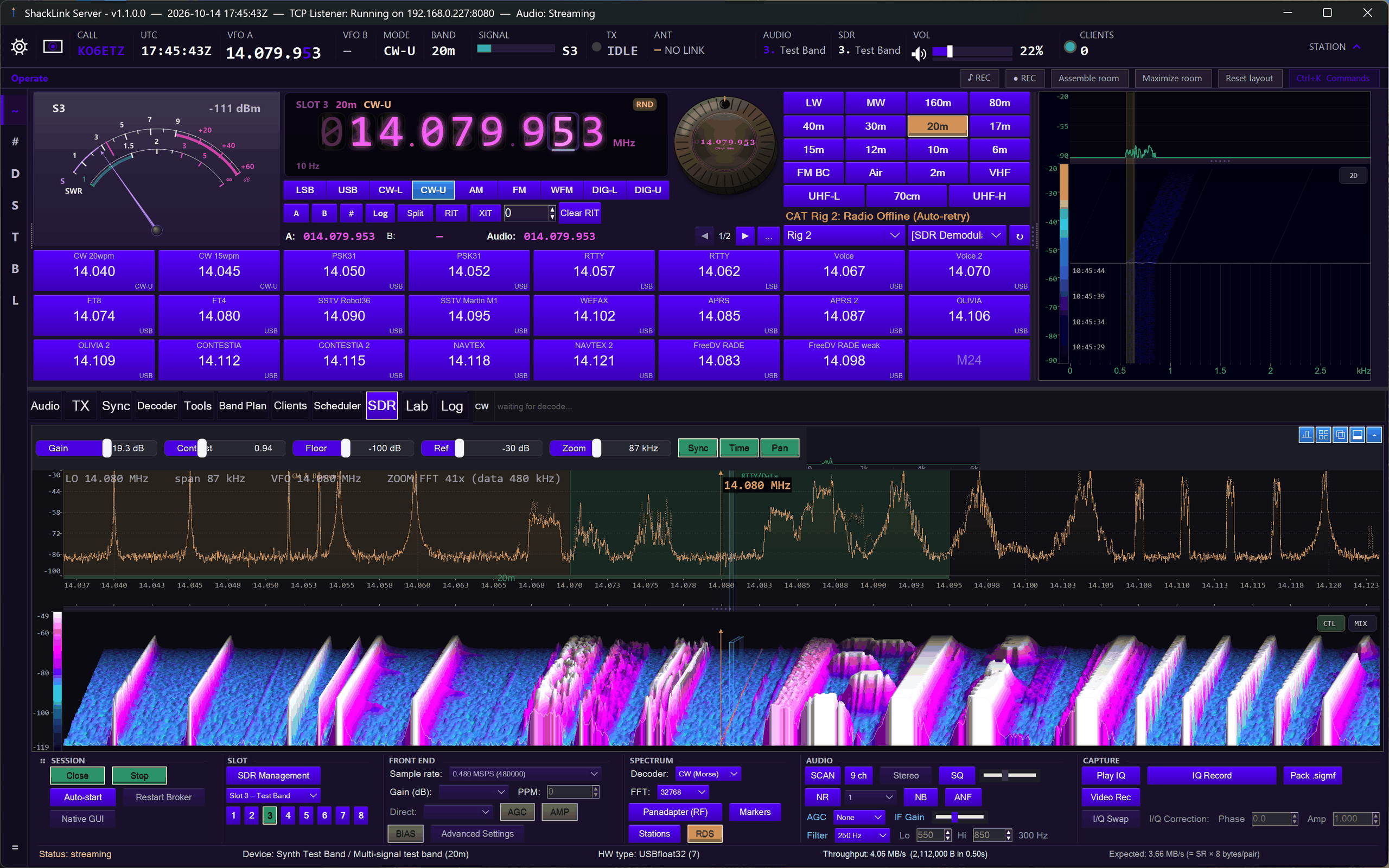
Neon theme
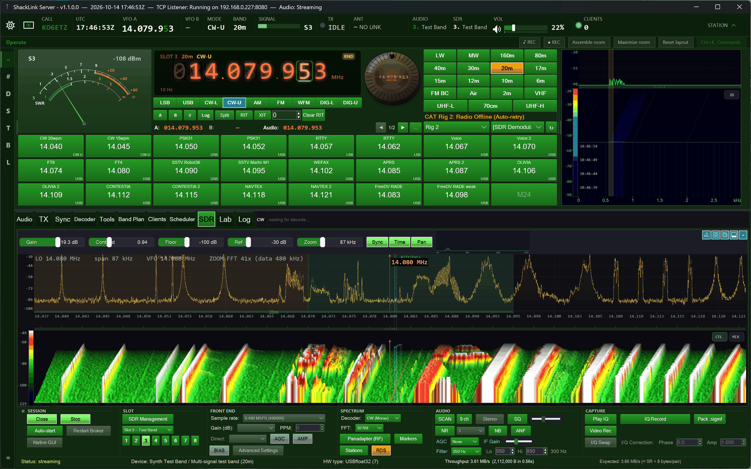
Green theme
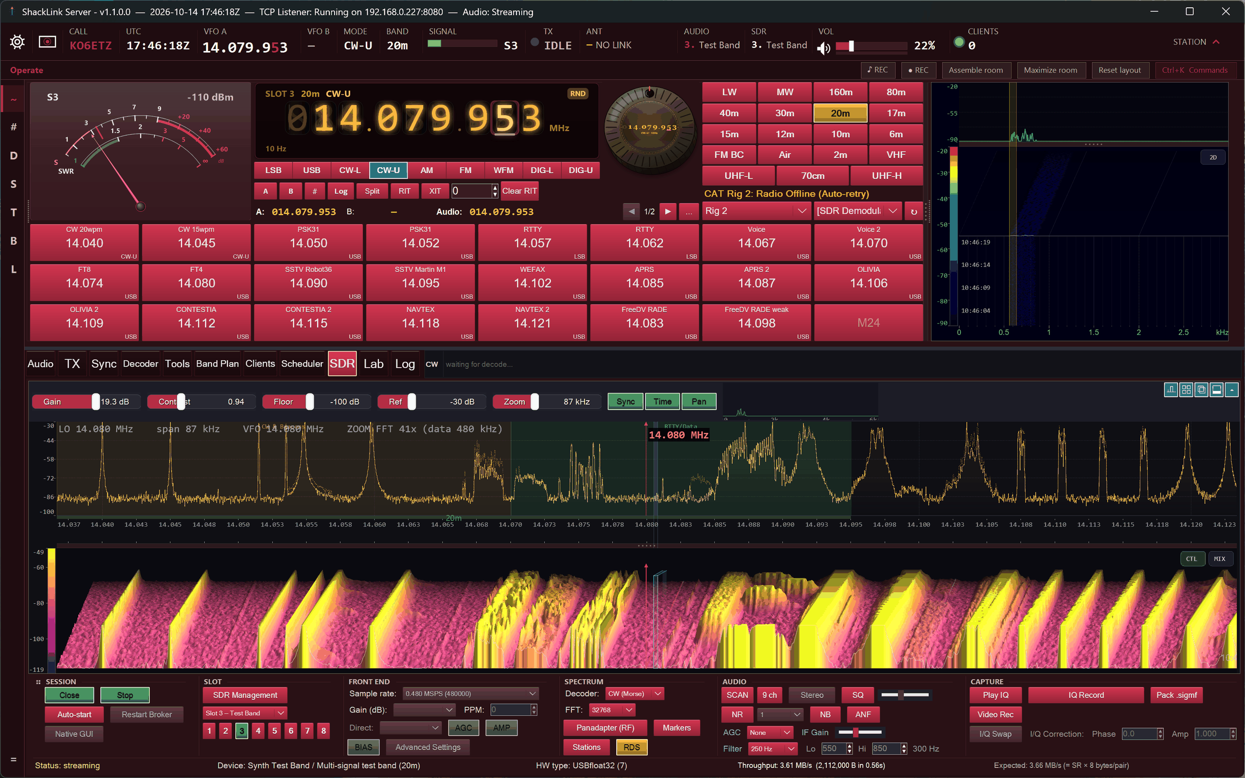
Plasma theme
Theme Submenu (Title Bar)
A Theme submenu is added to the window’s title-bar system menu on both the server and the desktop client, so you can pick a color theme straight from the system menu without opening the full Colors dialog.
Photo Panel (Right-Click Modes)
The panel beside the callsign strip is no longer a static photo. Right-click it to cycle its modes: Photo (the operator’s picture), Audio Visualization (live spectrum / waterfall / scope), Knob (a Freq-Knob rotary VFO dial), SDR Spectrum (a full spectrum-and-waterfall view of the slot you are listening to, with the SDR tab’s own right-click menu), Station Slice (the same view permanently zoomed onto the station you are listening to), Propagation (live solar data), Signal Alerts (the threshold monitor), Decoder (a display-only mirror of the current decoder’s output), and Greyline (a day/night terminator map). The two spectrum modes keep their own look — palette, zoom and levels set there no longer rewrite the SDR tab. New 2026-10: while the station’s speech transcript owns the decoder strip, Decoder mode shows the transcript with its translation indented under it; and on a narrow screen Hide photo panel on any of its menus switches the panel off (the Start menu’s Photo Panel tile brings it back). The selected mode is saved between sessions. The desktop client shares the panel and the Knob mode.
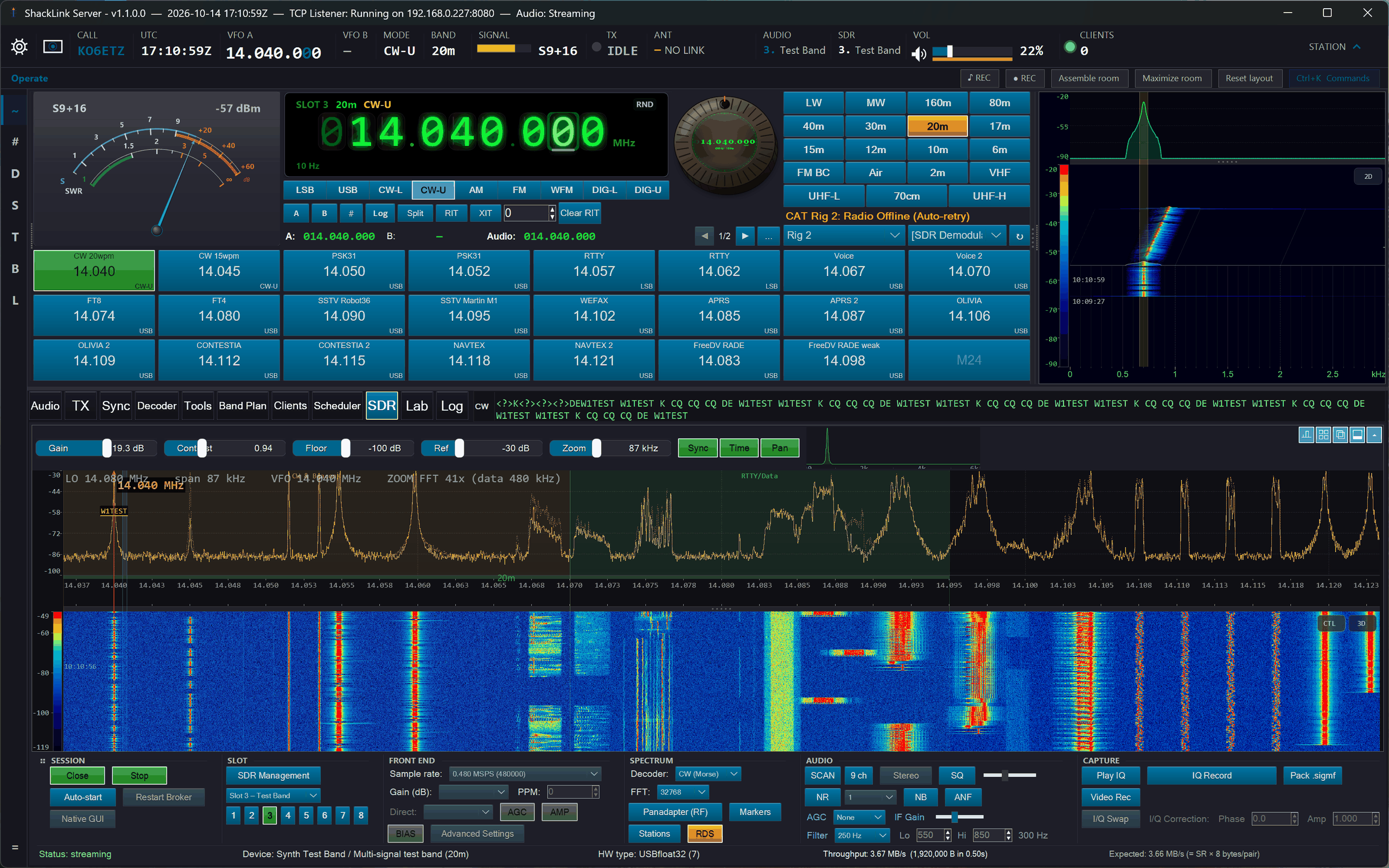
Audio Visualization mode
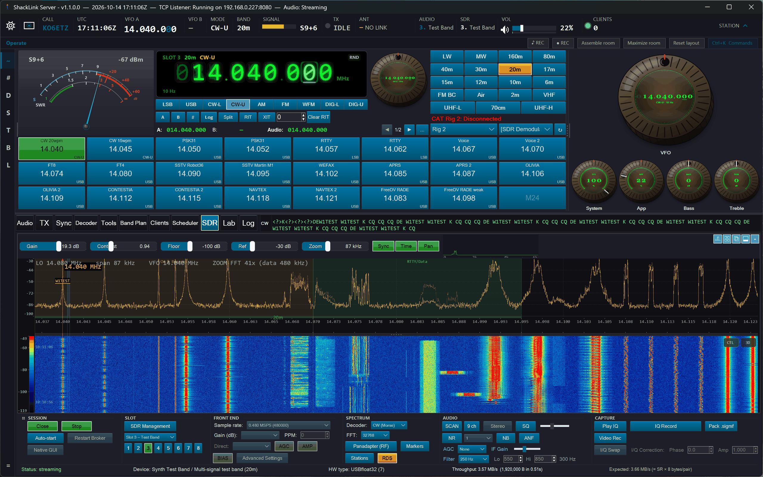
Knob mode: rotary VFO dial with monitor knobs

Propagation mode: live solar data
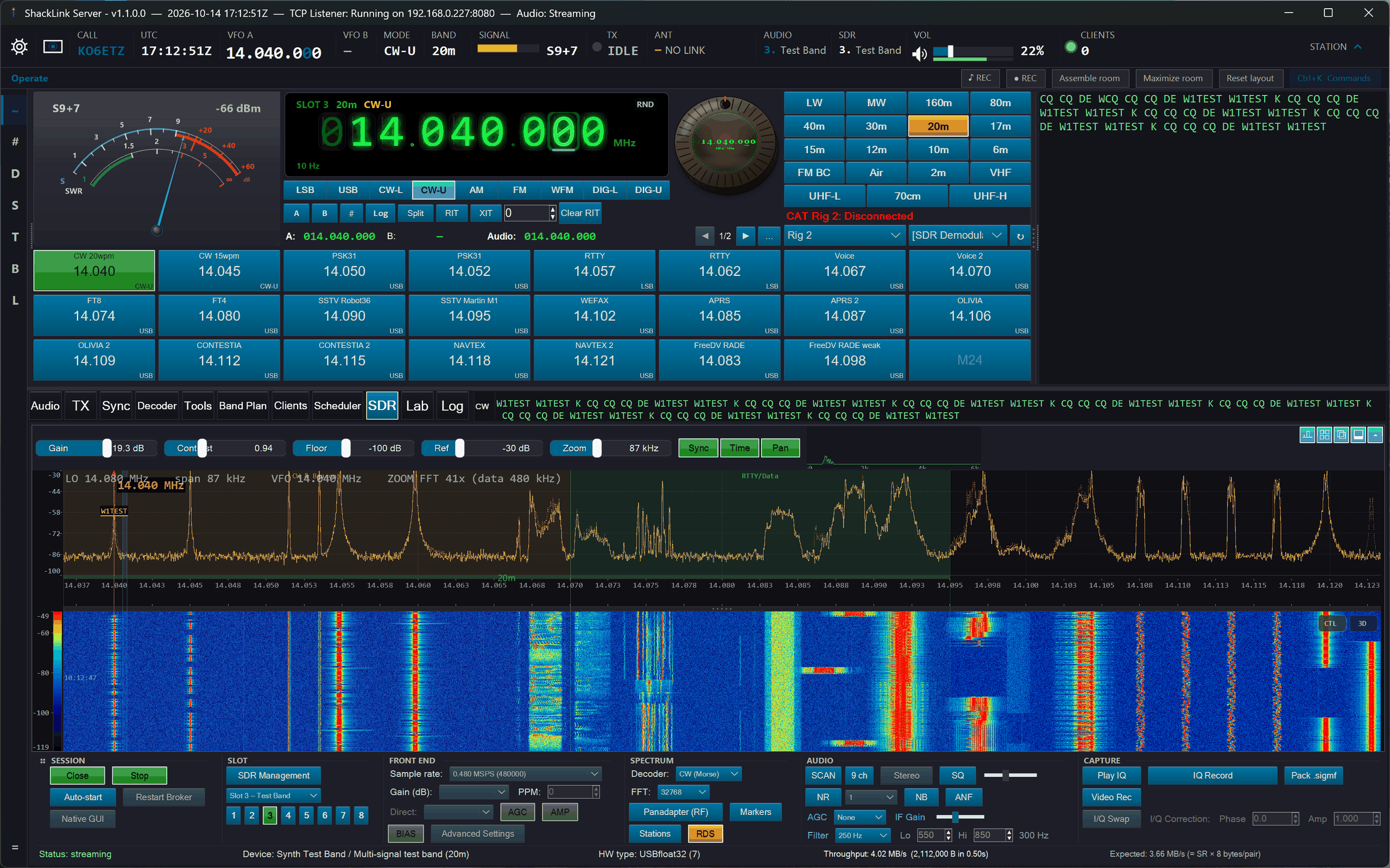
Decoder mode: mirror of the active decoder

Greyline mode: day/night terminator map (the Photo mode default is shown at the top of this page)
Tooltips Toggle
Toggle Show Tooltips in the Station Settings window (the flight strip’s gear) to enable or disable hover tooltips across all controls. Useful for learning the UI, then turning them off once familiar. Main form uses ApplyTooltips(); separate dialogs have their own ToolTip instances with dark-themed custom draw.
Broadcast Guide
A searchable station database covering shortwave broadcasts (EiBi + HFCC), local FM and AM stations (FCC, filtered by operator location), and NOAA weather channels. Quick-select band buttons span LW through 11 m plus FM and WX. Filter by frequency range, country, language, source, or station name. The On Now toggle shows only stations currently broadcasting based on UTC schedule. Track VFO auto-filters to the rig’s current frequency. Double-click any row to tune the radio (sets both frequency and mode). All filter settings persist between sessions. Available on both server and desktop client.
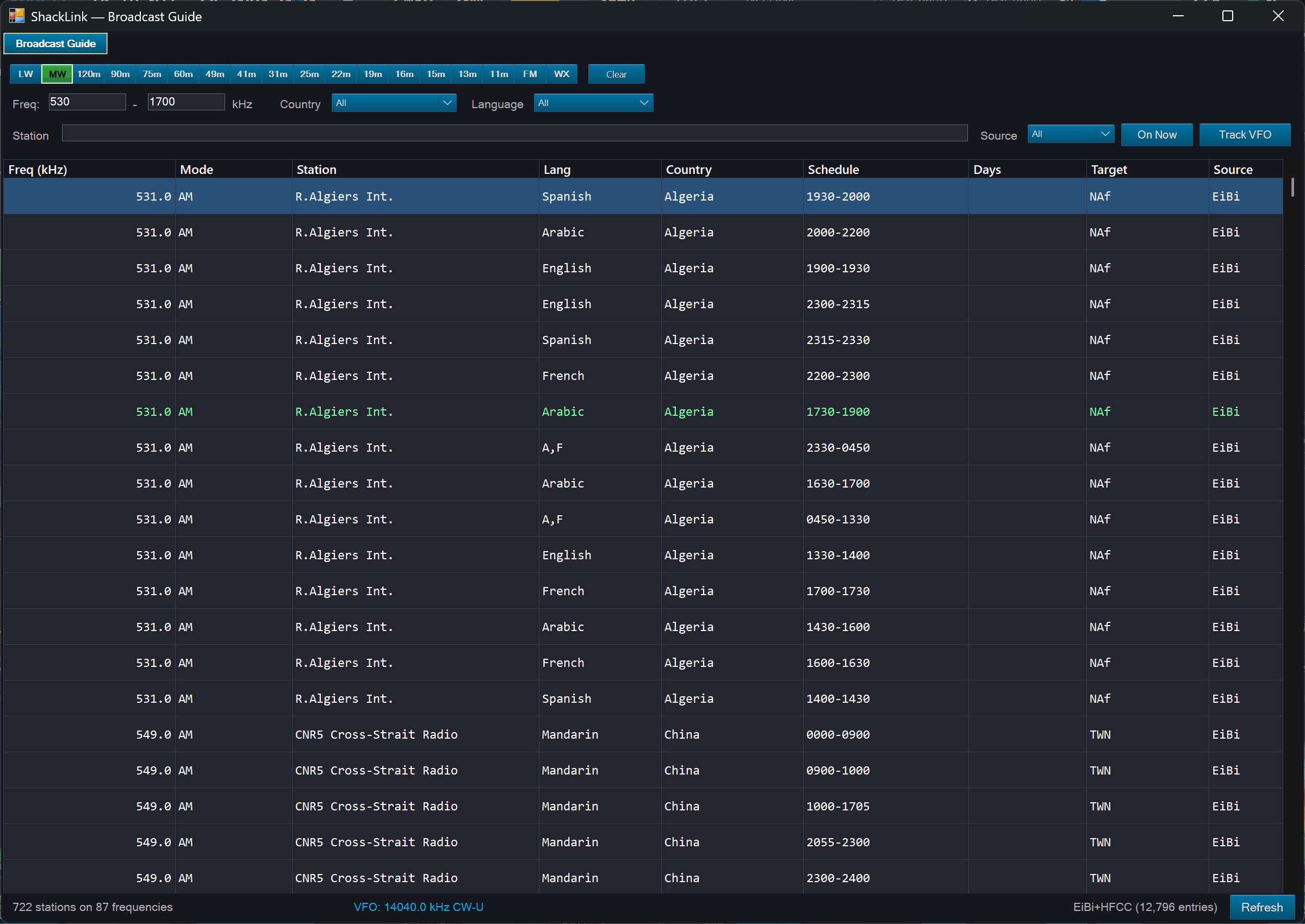
Broadcast Guide: shortwave / FM / AM / NOAA station database with band buttons, On Now filtering, and click-to-tune
Dashboards & Popouts
The Tools tab also launches a set of standalone operations dashboards, each in its own window for multi-monitor use:
- Propagation: live solar data from hamqsl.com (solar flux, A/K indices, band conditions).
- Greyline Map: day/night terminator showing where HF propagation peaks, with your logged contacts plotted as callsign chips and great-circle arcs to your QTH — on a flat map or, new 2026-10, a 3-D globe (see below).
- Band Activity: which band is open, to where and how strongly, from eight activity sources, with a coverage record so a band nobody was listening to is never drawn as dead.
- Signal Alerts: frequency / threshold / duration rules that fire Discord and Telegram webhooks or auto-record.
- Logbook (ADIF): built-in ADIF logbook viewer with search, sort, and DXCC country enrichment. Two-way QRZ.com sync (Station Settings → QRZ Logbook, needs a QRZ XML subscription and a per-logbook API key) uploads new QSOs and downloads QRZ’s, with auto-upload and a manual Sync Now.
- Spectrum Snapshots: a gallery of captured waterfall snapshots.

Greyline Map: day/night terminator with operator location

A later moment as the terminator sweeps across
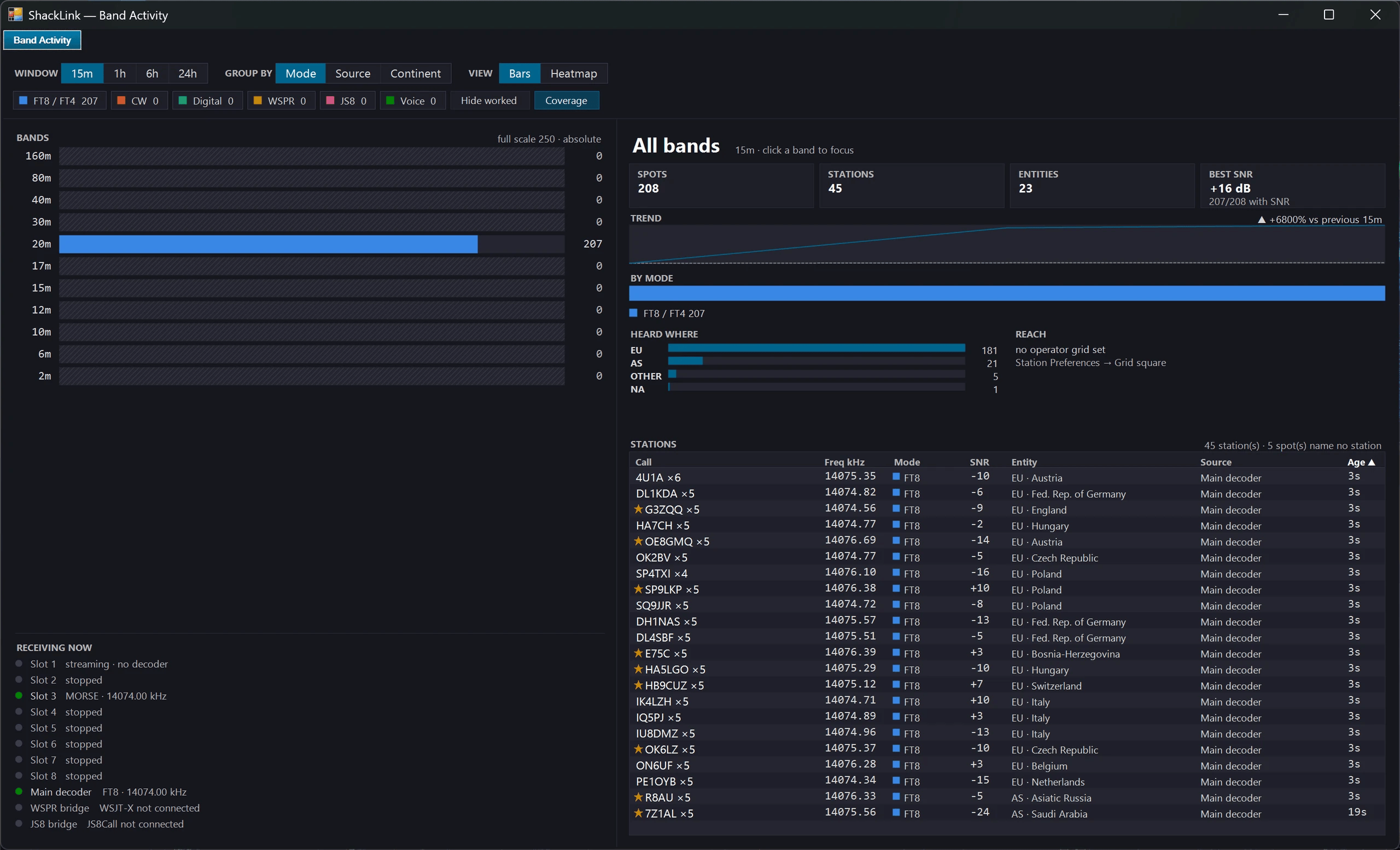
Band Activity: band-by-band activity over time, the trend, geography and a station table with click-to-tune
Propagation Map: Flat or Globe
New 2026-10. The propagation map has a Flat | Globe switch in its Layers panel. The globe draws everything the flat map draws on a 3-D Earth you can turn on any axis and zoom anywhere, and it covers the poles. The globe only loads the first time you pick it. The same map, with the globe, is on the desktop client and in the web client’s Map tab. New layers and settings:
- MUF: pick a band and the map shades where it should be open, from ShackLink’s propagation model run on the current sunspot number (it says it is a model, and which number it used).
- Greyline DX: paths with both ends in the greyline, the stations in it, and when the greyline opens and closes at your QTH and at a clicked point; ▶ play sweeps the clock forward.
- Ionosondes (measured MUF from KC2G, dimmed as each reading ages) and D-RAP, NOAA’s map of D-region absorption after a solar flare.
- Spot columns (globe only): the last 15 minutes of spots in each grid square, stacked by band.
- Hops (model) (globe only): each spot path drawn as equal hops off the ionosphere, clearly labelled a model.
- Satellites (AO-91, SO-50, the ISS and others, by the names operators use) with their orbits, footprints and next passes, and the Moon / EME window you share with a clicked point.
- City lights on the night side, and Worked DXCC, shading the countries of every entity in your whole log (approximate, and it says so).
- UTC or Local times and km or miles, plus map styles including satellite, street, topographic and dark.
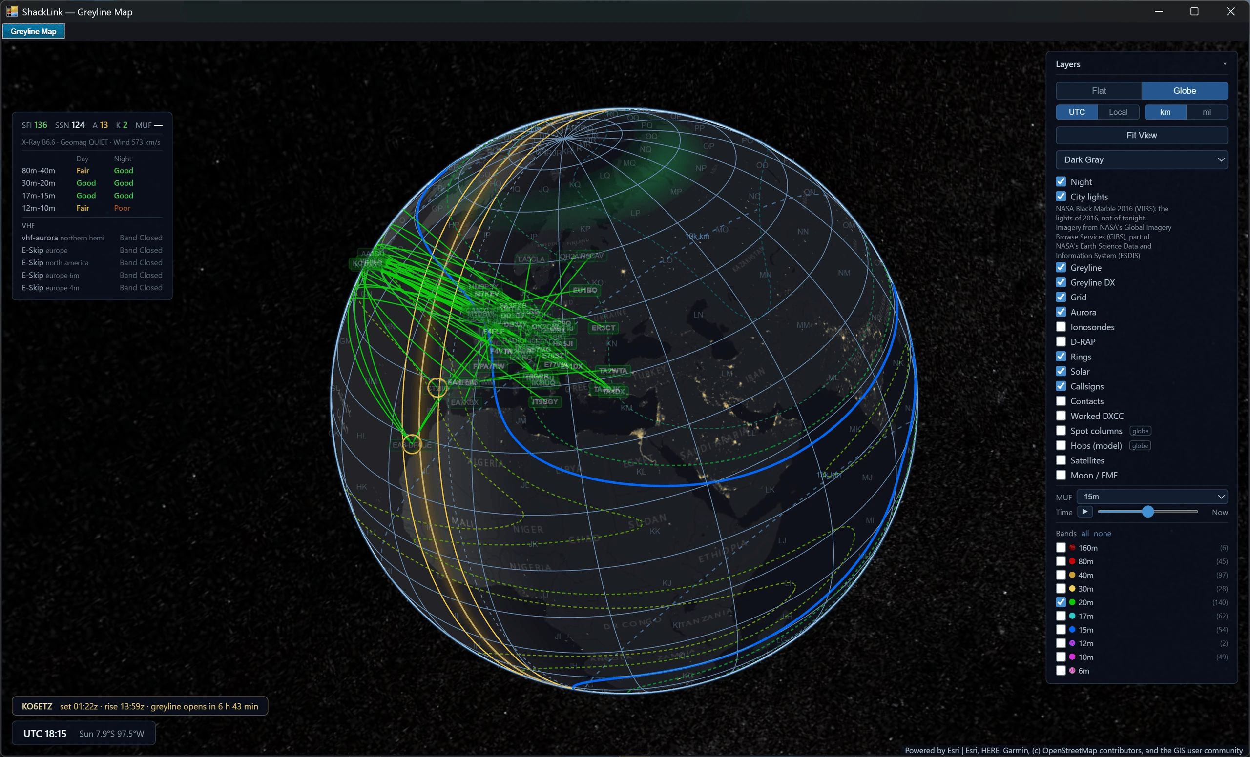
The propagation map in Globe view, with the Layers panel open
Callsign Strip & UTC Clock
The callsign strip shows the operator callsign next to an NTP-synced UTC clock (shared by server and desktop client), with configurable layout, font, and colors. The same NTP-synced UTC clock also appears in the server and client window titles.
Rotary Frequency Knob & Memories
The frequency-entry popup is resizeable and includes a Freq-Knob rotary dial: an endless VFO knob with per-digit stepping and flywheel spin, the same shared SkiaSharp knob library that powers the photo panel’s Knob mode. The station’s 48 memories store frequency, mode and a label, page across the faceplate, and open in an All Memories grid for quick recall.
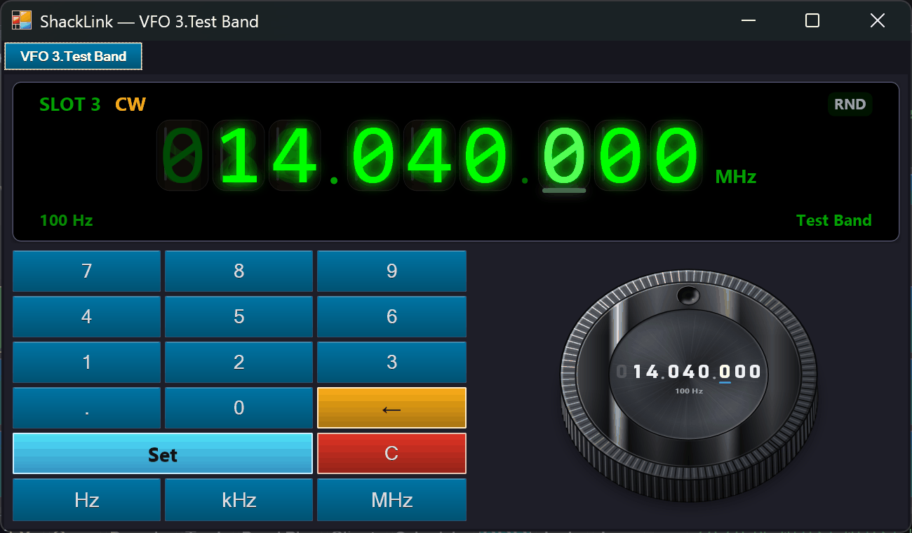
Frequency entry: keypad plus the rotary Freq-Knob for per-digit tuning
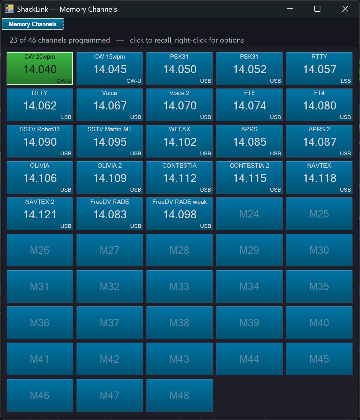
All Memories: all 48 channels as a resizable tile grid, click to recall, right-click to store / label / clear
Waterfall Painter (Spectrum Art)
The Waterfall Painter rasterizes text, an image, vector primitives, or an animation into audio tones across an SSB passband, so each tone lights one pixel column on a receiver’s waterfall: “waterfall art” drawn straight into the spectrum. Rehearse silently by painting into the Test Tone synth slot (every client sees it on the SDR stream), then transmit one-shot on air through the TX engine. It is SSB-only by physics: the sideband auto-follows the rig and there is deliberately no AM/FM (FM would smear the art).
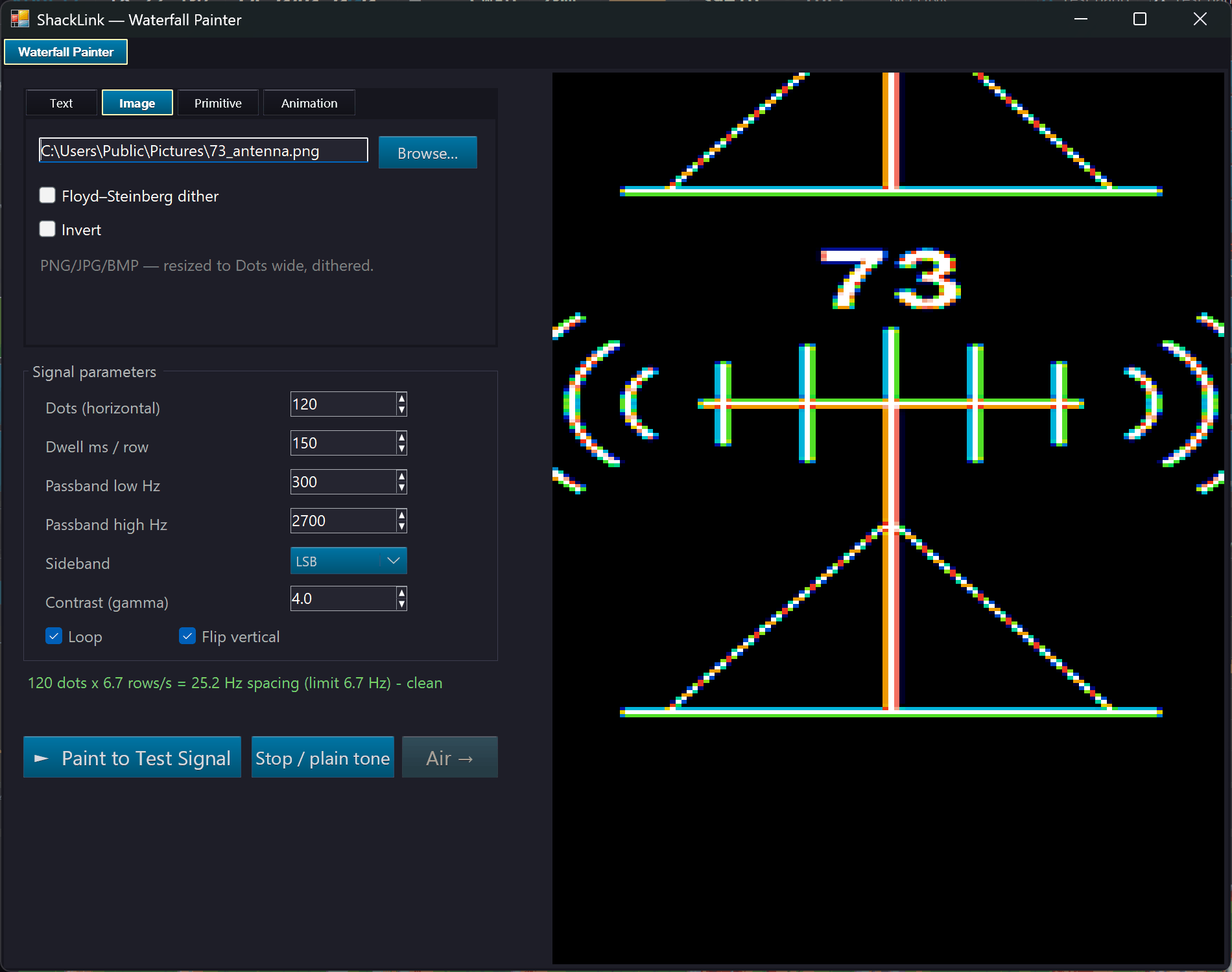
The Waterfall Painter window: source, gamma, and passband controls
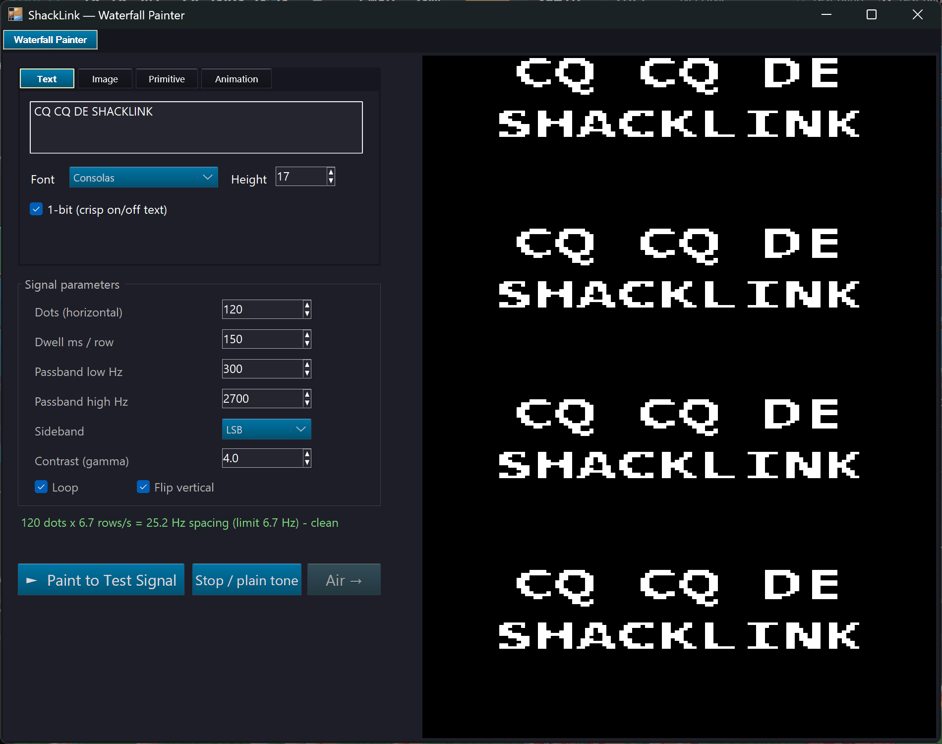
Rasterizing text into the passband

The art as received on the 2D waterfall

The same received art on the 3D terrain waterfall

Another camera angle on the received 3D art
Band Skimmer (Multi-Signal Decode)
A CW-Skimmer-style wideband decoder on the Tools tab. Instead of listening to one signal, it decodes every signal of a mode across a whole band segment at once (one decode lane per signal) off the raw I/Q of an SDR slot you already have running, and extracts callsigns into a live spot list. Point it at a slot, pick a band-plan preset or type a from/to range, tick the modes (CW, RTTY, PSK31 / PSK63, Olivia / Contestia, NAVTEX, FT8 / FT4 and Voice; with several ticked it classifies each signal and attaches the right decoder per lane), and hit Start. Each SDR slot can run its own skim, so several bands are skimmed at once. Because it taps the I/Q, it runs alongside the slot’s normal decoder and never touches the audio you’re listening to.
Confirmed callsigns show up as amber chips on the SDR waterfall (hover card + click-to-tune), spots feed the Band Activity dashboard and a session CSV, a watch-list callsign can fire a Discord / Telegram webhook, and stations you’ve worked before on the same band (from your ADIF log) are dimmed. The skimmer is server-owned, but the desktop, web, and mobile clients all show a live view console of the running skim: the same lanes, spots, and chips. CW copies best around 10–45 WPM; signals closer than ~50–75 Hz merge into one lane; FT8 / FT4 lanes are 3 kHz windows decoded by ShackLink’s own FT8 engine, while WSPR and JS8 are never skimmed, since WSJT-X and JS8Call decode those themselves.

The Band Skimmer: one decode lane per signal across a band segment, and the callsign spot list
Wideband Scan
Sweep one or several SDRs across a range far wider than any of them can see at once — a whole HF spectrum, every ham band, or the FM broadcast band — into a stitched panorama, a sweep-by-sweep waterfall, and a list of hits you can park a receiver on. Before anything moves, a preflight shows the hops, the sweep time, the resolution and the chance of catching a short signal, per radio. Frequencies that were not measured are drawn as gaps, never filled in. Keep one radio out as a listener so the search never stops while you listen, or as a classifier that visits each hit and labels its mode. The same engine runs Find stations. The desktop client can watch a scan live.
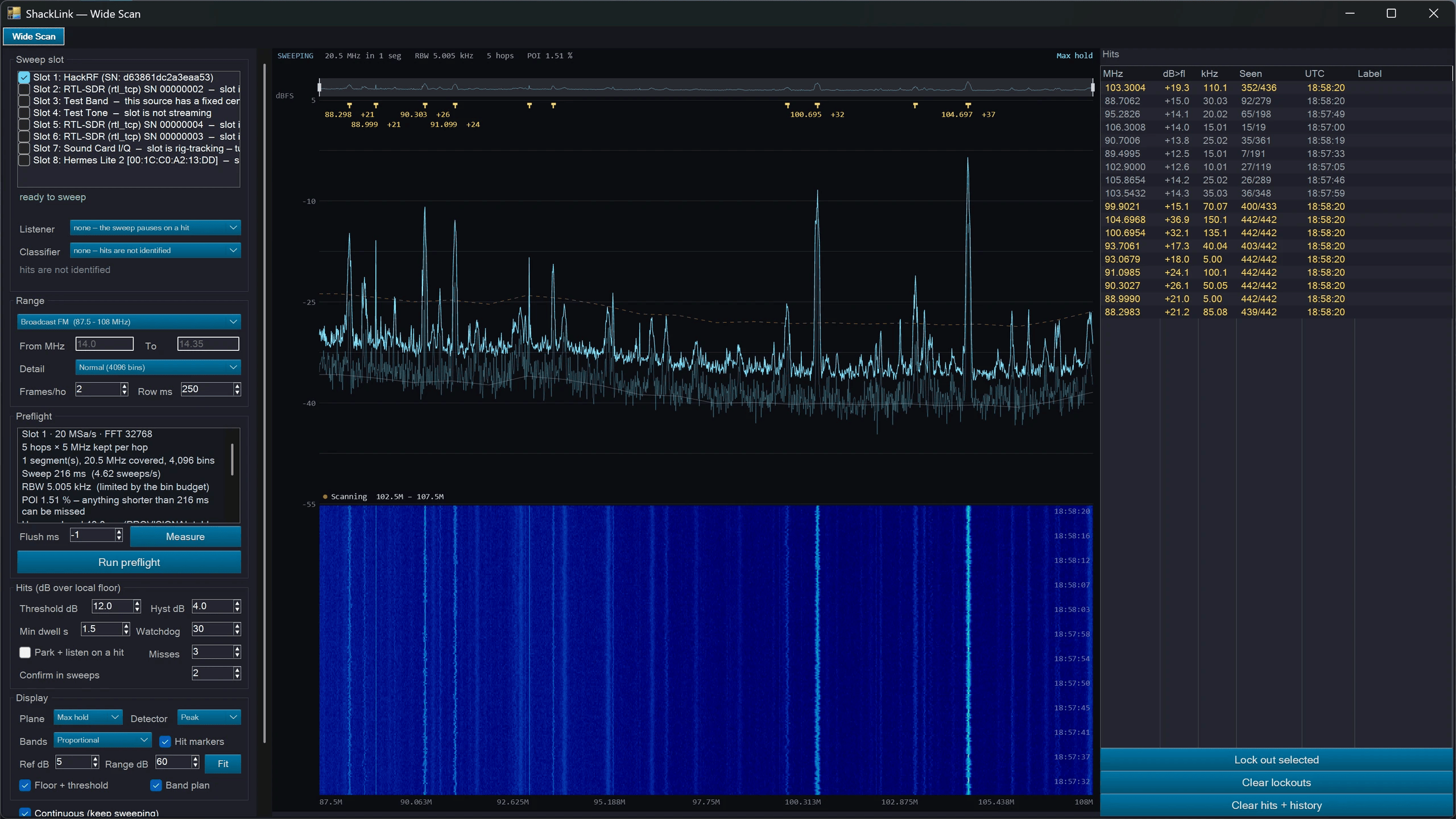
Wideband Scan: the stitched panorama, the sweep waterfall and the hits list
Voice Monitor
Live speech-to-text of the voice on the station’s own audio, with a streaming engine or a Whisper engine (optionally on the GPU), foreign speech transcribed in its own language, and optional live translation by a model that runs on this PC. Speech models download only when you agree. Transcription keeps running with the window closed. New 2026-10:
- On every client. The transcript and its translation reach the desktop, web and mobile clients, shown in the decoder display they already have while the station’s speech owns it. Watching starts nothing: the engines are switched on at the server.
- It survives a restart. The Voice Monitor keeps what it showed, colours included, and carries on from there after the server restarts; a reopened window picks up what was said while it was closed.
- Save transcript… and Load transcript… on the transcript menu, as rich text (keeping the colours) or plain UTF-8 text.

The Voice Monitor: the live transcript, one timestamped line per utterance
Scheduler
The Scheduler tab runs multi-step programs — tune, decode, record, transmit — once, daily, weekly, on an interval, or on demand. Programs chain together, start from built-in templates (CW Beacon, FT8 Session, WEFAX Receiver and test demos), and import and export as sets. A step can use an SDR slot as well as a rig, and a station step switches an antenna or powers the station up or down in order. Transmitting steps get band-plan checks, listen-before-transmit, a maximum TX time and automatic station ID.
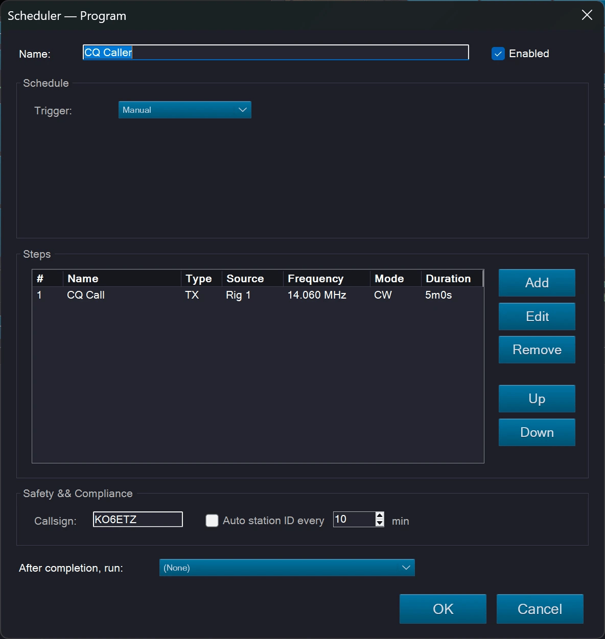
The Scheduler: programs, their steps and their schedules
📡 Antenna Switching
The station’s antenna switch, its per-band memory, and a transmit interlock that refuses to key into the wrong antenna.
ShackLink can own the station’s antenna switch: which antenna each radio and each receiver is on, which antennas are legal on the band you are working, what the software remembers per band, and whether you are allowed to transmit at all. It is entirely server-side — the catalogue, the drivers, the memories and the interlock all live on the server, and no client ever talks to switch hardware or decides what is valid. A station with no switcher configured behaves exactly as it did before this feature existed.
Two of eight kinds have driven real hardware. No RF has gone through any of them.
Serial / USB relay has driven an LCUS-8 / CH340 board on a COM port, and HTTP relay / Tasmota has driven an LC Technology ESP32_Relay_X4 running Tasmota v15. Everything else — the Antenna Genius, Modbus TCP, RemoteQTH, the EA4TX RemoteBox, and every HTTP vendor that is not Tasmota — is still exercised only against a simulated device that models the protocol’s hazards, which proves the message codec and not the hardware. Treat first contact with your own box as commissioning rather than as routine use.
These drivers switch the low-voltage control lines of a coax switch, never the coax; nothing here has been in a transmit path at full power on this bench.
Both real boards found faults a simulator structurally cannot, because a fake answers the protocol the manual documents and a board out of a box does not. A stock Tasmota ships its command API disabled and answers a probe with no reply at all — at the transport layer, indistinguishable from a box that is not there. A bare one maps no GPIO to a relay, so a healthy status reply contains no relay. A write-only serial board drops whatever lands on its port while a relay is physically moving, and because a selection breaks before it makes, the command it drops is the one connecting the antenna you just picked. Each of those now has its own refusal, naming a remedy that works.
The model
Devices are switch boxes, each with ports (a port feeds one radio or receiver) and positions (a position is one antenna socket). Antennas carry a name, a type, the bands they cover for TX and for RX, a receive-only flag, and the device / port / position they are wired to. Bindings attach a consumer — one of four rigs, or one of eight SDR slots — to a port, either as a claimant (it drives the switch) or as a plain consumer that only records which antenna feeds that receiver. That distinction is what lets a receive-only beverage on its own little switch follow an SDR slot’s tuning without ever touching the antenna your transceiver is using. Memories remember, per binding and per band, which antenna you chose.
Antenna Studio
Reached from the flight strip’s ANT cell, Antenna Studio has three tabs — Antennas, Bindings, Devices — plus a live diagram of the path from each consumer through its switch to the antenna currently selected. Antenna types are picked from a grid of seventeen technical elevation drawings rather than a list of words: wire dipole, inverted-V, end-fed, Yagi, hex beam, quad, log-periodic, vertical, trap vertical, whip, delta loop, magnetic loop, beverage, discone, dish, dummy load, and Unspecified. The Devices tab also carries switch discovery, the per-device Advanced editor, band-data output and storm park. On the Tools tab its tile is Antennas, Power.
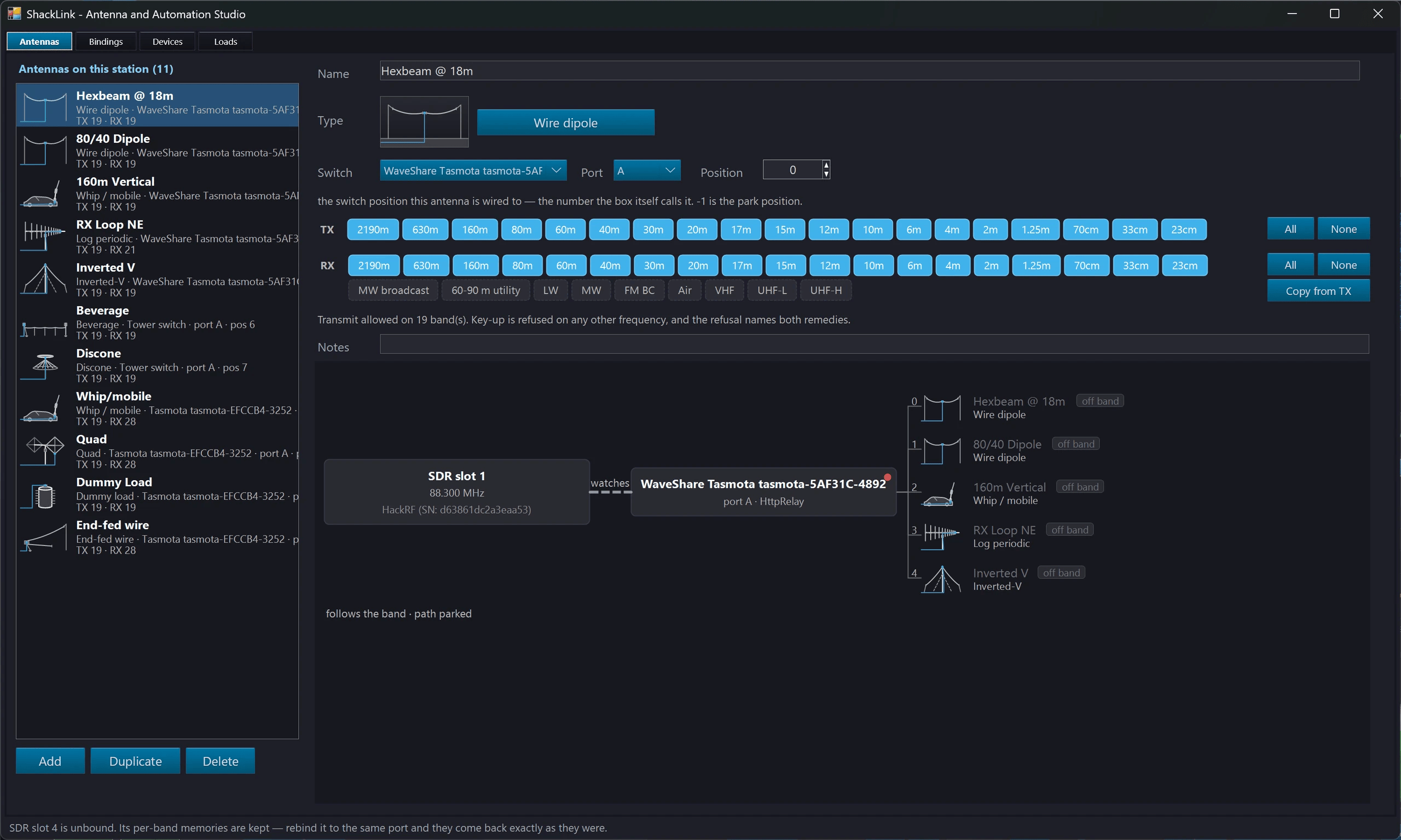
Antenna Studio: the antenna table, the bindings and devices tabs, and the live path from each radio through its switch to the antenna
Eight driver families
| Kind | What it is |
|---|---|
| Manual | The coax switch on your desk — a real driver, not a placeholder. |
| Simulated | A software switch, for trying the whole subsystem out with no hardware. |
| Antenna Genius | 4O3A’s networked antenna switch (v4 protocol), with subscriptions and readback. |
| HTTP relay | KMtronic, Tasmota, Shelly (both generations), ControlByWeb, Denkovi smartDEN, Numato. |
| Modbus TCP | Any Modbus coil-addressable relay board, e.g. Waveshare. |
| Serial / USB relay | KMtronic, Numato and LCUS / CH340 boards, over a COM port or ser2net. |
| EA4TX RemoteBox | The RemoteBox antenna switch, over serial or ser2net. |
| RemoteQTH | The RemoteQTH single-datagram UDP switch. |
Two things no driver here will ever do: there is no “toggle” anywhere in the subsystem — an antenna is always selected to an absolute position, because a toggle applied twice is a different antenna — and there is no pulse or flash timer, because a relay that opens again on its own is an antenna that changes by itself.
The TX interlock
Before every key-up the server checks the antenna path and refuses, in words naming both remedies, if the antenna is receive-only, has no TX rating on this band, the switch is disconnected, or the path is not confirmed. It covers all three ways of keying — text and CW modes, the Lab’s SDR transmissions, and voice, including a microphone or a footswitch, which is the likeliest way to put a carrier into a receive-only beverage.
| Confidence | Meaning | Transmit? |
|---|---|---|
| Unknown | We do not know where the RF is going. | Refused |
| Assumed | We wrote the selection and the box accepted it. No readback exists on this hardware, so this is its honest ceiling. | Allowed |
| OK | The device reported the position back and it is the position we believe you are on. | Allowed |
| Stale | It was read, but too long ago to trust. | Refused |
Assumed is deliberately not an alarm — on a write-and-assume relay board it is the best answer that exists, and colouring it red everywhere would train the operator to ignore the colour. A switch in the middle of moving does not refuse either: the key-up waits for it, bounded, and only a timeout is an error. Aborting a 15-second FT8 cycle over a relay settle would be the wrong trade.
The interlock asks two questions, and for a long time it asked only one. It checked how fresh the reading was and never whether the reading agreed with the antenna you had selected — and the selection is recorded optimistically, at the moment you pick, before the driver is commanded. So a switch sitting on a different antenna passed with a perfectly fresh reading. Four routes went through that hole, the worst being a restart onto a switch somebody moved while the server was closed — keying into the receive-only beverage the other radio has claimed, which is the failure this whole subsystem exists to prevent. All four refuse now, and every refusal names a remedy that works: three of them used to end “or set this consumer to Manual”, which lifts nothing, and the unconfirmed-path one said “re-select the antenna” while re-selecting what you were already on was a no-op.
Every selection writes the whole relay bank
Reported as “clicking the antenna buttons makes several relays connected at the same time”. A relay driver used to write only the difference between what it believed the board was holding and what you had just asked for — and if the belief is wrong, that omits the break: the relay that really is closed is never told to open. Two antennas paralleled onto one feedline, or none, both a wrong load on the finals at full power, and every readback agreeing, because the board really is holding what it was last told.
Three separate routes to a wrong belief had each already cost a station — a command dropped on a write-only board, a readback that expired while the board was still moving, and somebody else changing the board (its own web page, a phone app, a second controller), which no care inside the driver can prevent. So the belief is gone: every selection writes every channel, and the cached word is not consulted on the write path at all. It costs nothing electrically — there is no toggle here, so a channel told the level it already holds does not move — and it buys self-healing, which a difference-only write cannot have. Note that the interlock had been refusing the whole time and the relays were still paralleled: a refusal is not a repair.
The confirmation poll had to slow down with it. Its interval came from the device’s settle time, default 15 ms — so a stock station re-opened a TCP connection to a Wi-Fi board every 20 ms for the whole confirmation window, and Tasmota answers requests from the same single loop that works its command queue. The wait was starving the switch it was waiting for, and a perfectly healthy selection came back blaming the wiring, the index base and the active-low setting, all three of which were correct. Each driver family owns its own poll interval now, and an operator who had already worked around this by raising the settle time keeps their setting.
When a switch will do nothing, it now says so
Three configuration mistakes used to leave a switcher completely inert while every readback agreed. An antenna with no relay word under a custom mask encodes to zero, so the board is told to energise nothing on every pick — a real station ran eight antennas that way. An antenna still on the park position is worse, because park is what a brand-new antenna is created on, so a station where nobody typed the position numbers has a switcher that is inert on every pick. And an antenna with no bands at all resolves to park for a Follow consumer while every picker greys it out, so the table looks right. Each now raises an amber banner on the Devices tab naming the antennas affected, and repeats itself where the decision is actually made — deliberately not on the link lamp, because “the cable is up” and “this configuration can select an antenna” are different questions.
Finding switches
Discovery has four ways of looking and only one of them asks: an Antenna Genius beacon, mDNS for Shelly boards, this machine’s serial ports — and a network scan, because whole families announce nothing at all. Tasmota, Modbus, the EA4TX RemoteBox and every classic relay board could previously only be typed in by hand. The scan is a separate press and the button names the subnet it is about to knock on: on the one discoverer that touches machines that are not yours, the caption is the consent. Its first pass writes nothing — a TCP connect and a close — and only the addresses that answer are asked which relay board they are. A probe may never be a write, which is enforced rather than intended: on this device class “it is only a GET, so it is safe” is false, because Tasmota’s control channel is a GET. A network wider than a /22 is refused in words rather than quietly truncated, since a silent cap reads as a completed search.
The manual switch
If the switch in your shack is a rotary knob on the desk, ShackLink still owns everything above it — the antenna table, the band coverage, per-band memory, the path diagram, the flight-strip cell and the interlock. Its contract is simply honest: nothing happened when we asked. A selection leaves the confidence Unknown, which the interlock has always refused; confirming that you turned the knob reaches Assumed, the permanent ceiling, so it is one confirmation per change rather than a nag on a timer. A reminder window lists the knobs that are unaccounted for — derived from your bindings, not from a queue of requests, which is what makes it right at session start, when every knob is unaccounted for.
Band data out
Two independent ways to tell the rest of the station what band you are on, both off by default. A binding can carry Yaesu 4-bit BCD band data on a device’s relays instead of an antenna — sharing a board with antenna positions, since the driver composes the bits on the way out and strips them on the way in. Or the server can emit the N1MM-format RadioInfo UDP broadcast on port 12060, the packet Green Heron Everyware, microHAM’s TRIO, the EA4TX RBM and the open ESP32/Arduino decoders already listen for. That one carries a frequency and lets the consumer decode the band, which is why it has none of the BCD holes — no 60 m ambiguity, no WARC merge, no vendor disagreement.
Band data is invisible to the TX interlock, and must be: an interlock refusal is about which antenna carries RF, and band data carries none. It is deferred under live TX, which is a different question — a relay moving under key is a hot switch of the amplifier’s input.
Receiving on a different antenna
New 2026-08-27. A binding can receive on one antenna and transmit through another — an RX-only Beverage for listening while the beam stays the transmit path. Only the transmit path guards a key-up; an unconfirmed receive antenna is a warning. Every client gains a Receive on choice once a second path exists, and a transmit change no longer drags a separate receive relay along with it.
Storm park
One latch grounds the feedlines: every claimant is parked, band-follow applies nothing, and a manual pick is refused in words. Since 2026-08-31 it can also disconnect everything, arm itself on a severe-thunderstorm or tornado warning for the station (US National Weather Service) and take the station’s mains down with it. The frequency is still recorded, so releasing lands on the right antenna without waiting for the dial to move. It is persisted, and that is the point rather than a convenience — a PC that reboots during a thunderstorm must come back parked. Arming it from a remote client is deliberately not offered: it is a safety action taken by somebody who can see the sky.
On every client
All five surfaces carry the antenna and none of them decides anything: the server console, the desktop client, the web client, the mobile app, and the Home Assistant radio card. On the two desktop apps the picker is the flight strip’s ANT cell — a duplicate row on the faceplate was retired in 2026-08, leaving exactly one antenna picker per window — and it is a panel of cards, a thumbnail of each antenna’s type beside its name and its switch port. A rig reaches one switch port, so its list is short; antennas on other ports are shown greyed under their own switch’s heading rather than hidden, because naming which antennas are out of reach is what tells you the binding needs changing. The row does not exist at all until the server says this rig is bound and the catalogue is non-empty — a station that has never configured a switcher gets no control, not a dead one. Nothing is applied optimistically: a client sends the pick and redraws only from what the server says actually landed, which is also what makes a refusal visible.
Two services that already knew everything about the station except this now know it too: MY_ANTENNA is stamped into every logged QSO when the rig is bound and something is selected, and two webhooks — antenna control stopped working, and something was refused permission to transmit — join the eight that already exist. Deliberately not “the antenna changed”: on a contest station that is a message a minute, and a notification stream nobody reads is worse than none.
🔌 Station Power
The same relay boards that switch antennas can power the station — in order, with the load itself as the witness.
A switched load is anything powered through a relay ShackLink already drives: a transceiver, an amplifier, a rotator, a mast-head preamp. It is configured on Antenna and Automation Studio’s Loads tab and operated from Station Power on the server, the desktop client, the web client and the mobile app.
- The load is the witness, not the relay. Name the rig or SDR slot a load powers and its state reports whether that is answering — which catches a blown fuse, a front-panel switch left off, or a relay wired to the wrong thing.
- Power up / Power down walks the station in one order used both ways, waits for each step to come up before the next, holds an amplifier’s cool-down, and stops at the first step that fails, saying which load.
- A storm can disconnect every antenna on a severe-thunderstorm or tornado warning for your location (US National Weather Service) and, if you ask, take the mains down too. Nothing ever powers the station back up by itself.
- A scheduled program step can switch an antenna or power the station up or down.
- Every press is confirmed, every time, naming the load; refused under a live carrier and, for power-up, while the antennas are storm-parked. A pulse-type load with nothing to report its state can only be pressed at the station.
All of it is built and tested in software; nothing has yet switched a real load on mains.
⇄ Full Duplex
One named receiver keeps listening while the station transmits; every other receiver still goes deaf.
The satellite case is the headline: the rig works the uplink and an SDR slot hears the downlink. It also covers a second radio listening to a pile-up while you call, and hearing your own signal through a coupler. Arm it in Antenna and Automation Studio, or from the web client.
- Arming changes nothing on its own. The pairing is checked when you arm it and again at every key-up; if the receiver has been retuned or moved to another antenna in between, the transmission is refused rather than the receiver silently going deaf.
- A shared antenna is never allowed. Same-band pairings, unknown isolation and an unprotected receiver can be accepted, and your consent is recorded for exactly the transmitter, receiver, antennas and bands you were shown.
- Receive protection: a relay can take the receiver out of line (or pad it) before anything radiates, and nothing keys until it has confirmed it moved.
A station has transmitted and received at once, a protection relay has moved under a key-up, and the coupling between two real antennas has been measured. How much RF a given receiver survives has not been.
🌌 Multiband
Every streaming SDR slot on one stitched frequency axis, where a click tunes and listens.
Multiband puts every streaming SDR slot on a single stitched frequency axis — one spectrum and waterfall covering everything your receivers can hear, side by side in true frequency order. It is the Lab’s stitched axis promoted to an operating surface, and it runs on the server and the desktop client alike.
- Click anywhere covered → that slot tunes and you start listening to it. Ctrl+click tunes the rig instead.
- Wheel steps the station; Ctrl+wheel zooms; Ctrl+Shift+wheel moves the reference level; the arrow keys step the listened station.
- A click on a frequency nothing in the fleet covers is refused with the nearest covered edge named — never a silent nothing, and never an LO command, which would drag every decoder and skimmer riding that slot.
- A coverage ribbon puts the gaps the stitched axis hides back on screen in true scale, so 200 kHz of gap is distinguishable from 20 MHz of it.
- Signal-ID, skimmer and RDS chips render per slot, with the band plan, memory bank and DX spots. Anything in a stitched gap is skipped rather than snapped to a seam.
- LEVELS gives every band its own Trim (amplitude offset) and Cut (floor clamp), plus an RF gain column on the server. The shared axis’s Ref and Floor are deliberately not per band — one plot, one labelled dB scale.
- Activity dots, ribbon heat, fleet presets, a right-ear dual watch, and per-slot Identify Signals / Skim Callsigns quick-arms.
The page badges its amplitude axis rel and offers no markers, limit masks or dBm calibration — per-slot trims are live here, so a calibrated absolute number would be a lie. “Available on the control” is not the test; “correct on this page” is.
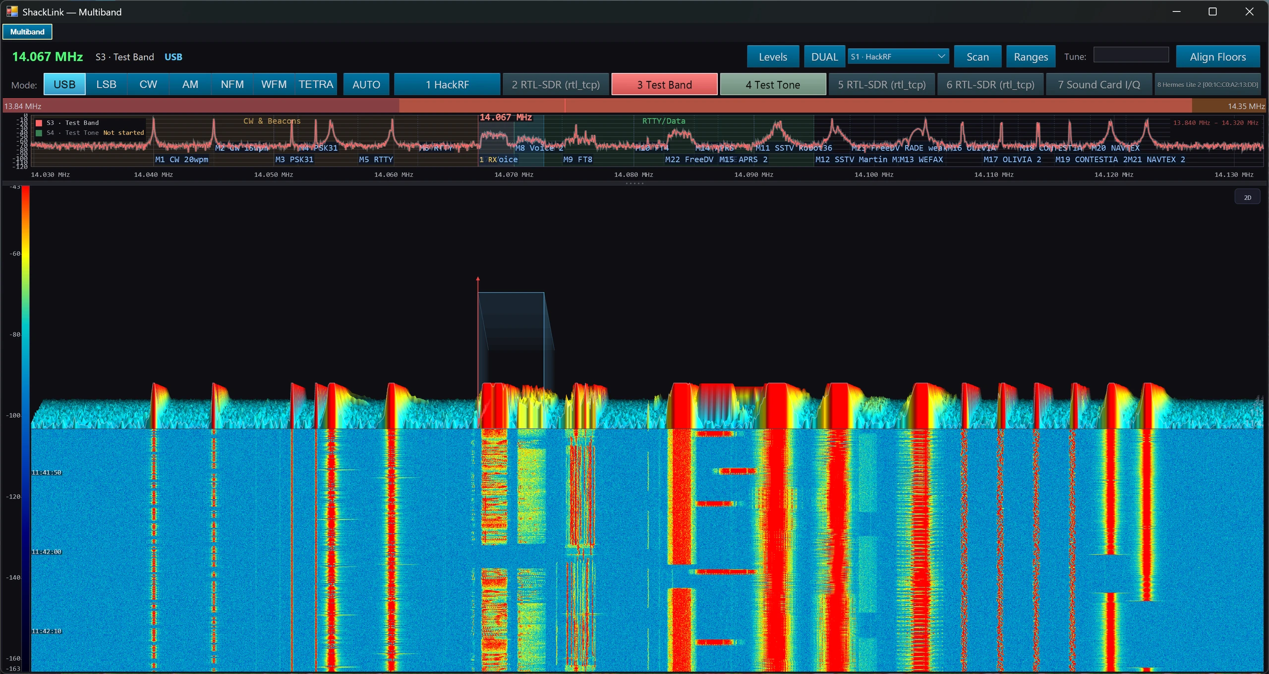
Multiband: every streaming slot on one stitched frequency axis, with the coverage ribbon underneath
🔄 Device Sync (Sync Tab)
Link rigs and SDR slots together so frequency and/or mode changes on one push through to another.
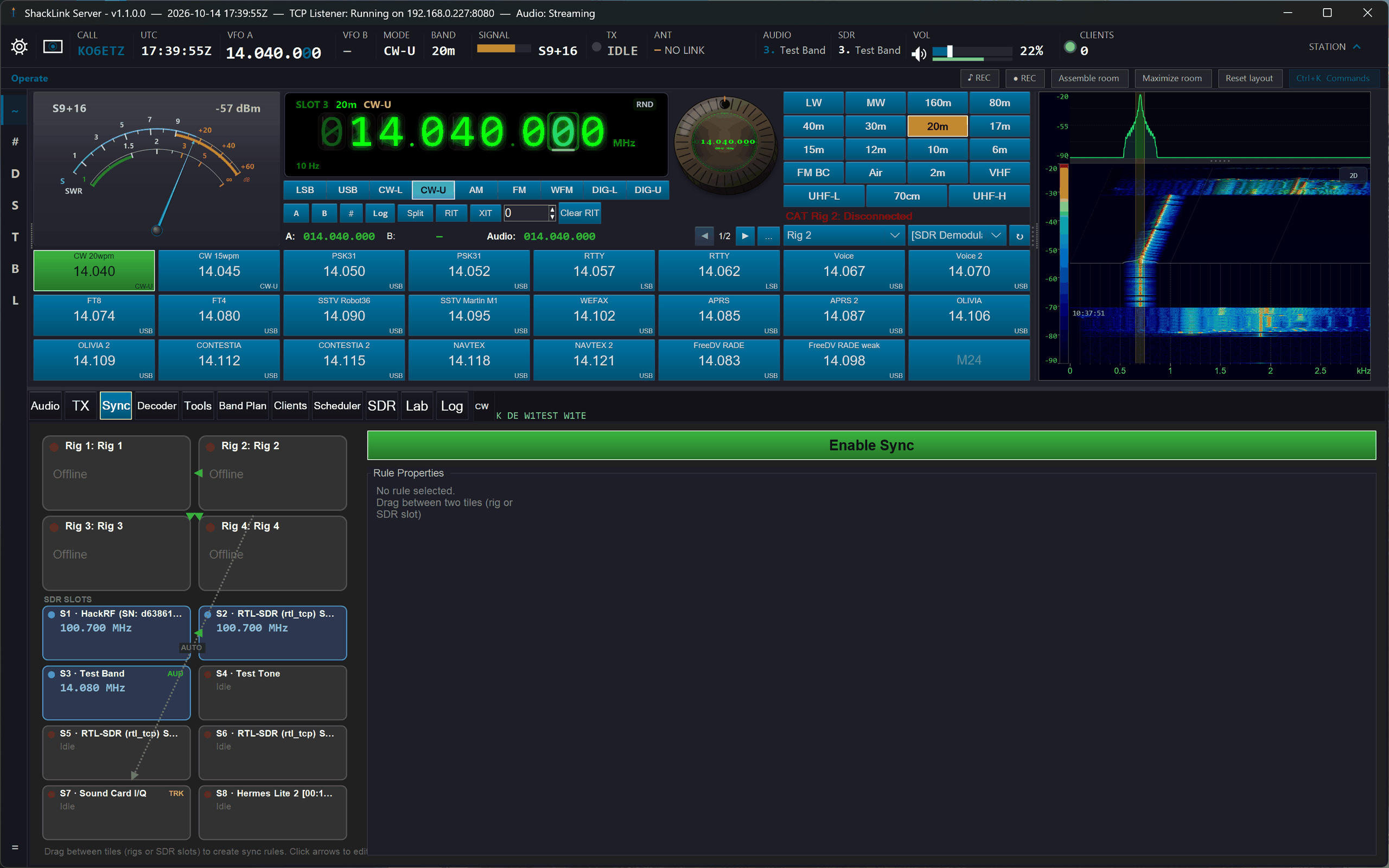
The Sync tab: four rig tiles and eight SDR slot tiles wired with rule arrows (amber dashed = automatic Track Rig)
The Sync tab lets you wire up rules between equivalent devices: OmniRig’s four rigs and the eight SDR slots (rig→rig, rig→slot, slot→rig, slot→slot). Useful for transverters (source on IF frequency, target on RF with a fixed offset), dual-radio diversity setups, a monitoring receiver or panadapter that should always track the main rig, or making one SDR’s Lab trace follow another. For rigs a rule reads/writes VFO-A; for SDR slots it reads/writes the slot’s LO / center frequency (in-span demod retunes don’t fire rules).
Creating a Rule
- Open the Sync tab: you’ll see four rig tiles (Rig 1 – Rig 4) and eight SDR slot tiles (S0 – S7, empty slots dimmed)
- Drag between any two tiles. An arrow appears representing the rule.
- Click the arrow to select it. The rule’s properties appear on the right.
- Build chains by adding more rules (Rig 1 → Rig 2 → Slot 3): a change at the head applies to every hop in one pass. Bidirectional pairs and accidental cycles are safe: each device is written at most once per change.
Per-Rule Properties
- Offset: Frequency offset (MHz) added to the source before writing to the target. Can be negative. Typical use: transverter IF offset.
- Invert Sideband: USB↔LSB, CW-U↔CW-L, DIG-U↔DIG-L. Applied when Sync Mode is on.
- Sync Frequency: Copy source frequency (+ Offset) to target (rig VFO or slot LO).
- Sync Mode: Copy source mode (optionally inverted) to target. Rig→slot maps onto the slot demodulator; slot→rig maps the demod mode back.
- Enabled: Per-rule on/off, disables without deleting.
Automatic Rules
SDR slots with Track Rig on show an amber dashed AUTO arrow from the currently selected rig, the rig-tracking mechanism made visible. Auto rules are read-only; deleting one turns Track Rig off for that slot. Slot tiles carry AUD (audio-active), TRK (Track Rig) and IF (IF-mode panadapter, LO pinned) badges.
Global Enable + Logic
The Enable Sync toggle at the top right is a master kill switch for the whole engine. For a change on the source device to propagate to target, three conditions must all be true:
- Global Enable Sync = on
- Per-rule Enabled = on
- At least one of Sync Frequency / Sync Mode = on
The engine separates genuine changes from its own echoes by value (a device reporting back the value just written to it is ignored), rate-limits each rule to ~3 writes/s, and cuts rule cycles deterministically (each device written at most once per change). Rules targeting a rig-tracking or IF-locked slot are skipped (those mechanisms own that slot’s LO); a tracked slot’s machinery moves don’t fire its outgoing rules. Manual moves do. All rule data (offsets, toggles, enabled states, global enable) is saved automatically on every change and restored on the next run.
📋 System Requirements
What you need to run ShackLink Server and clients.
🖥 Server Computer
- ✓ Windows 7/8/10/11
- ✓ .NET Framework 4.7.2+
- ✓ OmniRig v2.0 or later installed (hb9ryz.ch/omnirig)
- ✓ Sound card (for audio)
- ✓ Network connection
💻 Desktop Client
- ✓ Windows 7/8/10/11
- ✓ .NET Framework 4.7.2+
- ✓ Network to server
- ✓ Audio output device
🌐 Web Client
- ✓ Chrome 66+ / Firefox 76+
- ✓ Safari 14.1+ / Edge 79+
- ✓ Network to server
- ✓ Any OS supported
🏠 Home Assistant
- ✓ HA 2021.12 or newer
- ✓ Network to port 8084
- ✓ Lovelace dashboard
📱 Cross-Platform App
- ✓ Windows 10+, iOS 14+, Android 8+
- ✓ Network to port 8080
- ✓ WiFi recommended
📻 Radio Equipment
- ✓ OmniRig-supported radio
- ✓ CAT interface
- ✓ Audio cables (optional)
🔧 Troubleshooting
OmniRig Won’t Connect
- Check if OmniRig is running and configured properly
- Verify COM port settings match your radio
- Restart OmniRig and the server application
Clients Cannot Connect
- Verify the server is running and accessible
- Check firewall allows ports 8080, 8081, 8082, 8084, 8085 (and UDP 8081 for service discovery). Station Settings → Server → Configure Firewall does this for you
- Ensure client has correct server IP address
- Try pinging the server IP from the client machine
- If the TCP listener will not start, another program already holds port 8080. The server now names it in the window caption and the log, with the fix. A common one is the NI Application Web Server installed with NI-VISA, which starts with Windows; stop it or set it to Manual.
- If remote clients are suddenly refused, check the Security panel in Station Settings: when the authentication settings file cannot be read, the server keeps authentication on and says so there.
No Audio
- Select correct audio input device on server
- Check sound card levels in Windows Mixer
- Verify audio cables are connected
- Ensure audio streaming is started on server
- Check client volume is not muted
Digital Decoder Not Working
- Enable the decoder checkbox on server
- For CW: Adjust decoder mode (Speed/Accuracy) based on signal conditions
- For RTTY: Ensure the signal uses standard amateur radio parameters (45.45/50 baud, 170/425/850 Hz shift)
- For FT8 / FT4: with the default WSJT-X engine nothing decodes unless WSJT-X is running; choose Native in the FT8 panel’s Engine selector to decode without it
- Ensure audio streaming is active
- Check audio levels (too quiet or too loud affects decoding)
- Monitor the signal scope and quality indicators